RC networks

Ron H

Joined Apr 14, 2005
7,063
bobbyk said:
How did you get 1.476? I've never been able to get a gain that large!
How many R's and C's did you need?

And thanks for your interest in this question! I think it's fascinating!
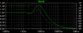
I'll post the schematic. Still curious why you wouldn't, until I spilled the beans.
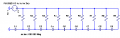
I shrunk the schematic to get it to fit on the forum, so I am listing the component values here:
R1=100, C1=1u
R2=316, C2=316n
R3=1k, C3=100n
R4=3.16k, C4=31.6n
R5=10k, C5=10n
R6=31.6k, C6=3.16n
R7=100k, C7=1n
R8=316k, C8=316p
R9=1Meg, C9=100p
Notice that the values are evenly spaced on a log scale. I don't know if this is optimum.
I suspect that the gain approaches 1.5 asymptotically as the number of elements approaches infinity, but I wouldn't know how to prove it.
EDIT: The output is the R9-C9 junction.
EDIT: I changed all the log2 capacitors and resistors to 0.5, i.e.,
R1=100, C1=1u
R2=500, C2=500n
R3=1k, C3=100n
R4=5k, C4=50n
R5=10k, C5=10n
R6=50k, C6=5n
R7=100k, C7=1n
R8=500k, C8=500p
R9=1Meg, C9=100p
and the max gain went down slightly, to 1.470.
 

Attachments

Thread Starter

bobbyk

Joined Jun 13, 2006
12
That IS a really great network! G=1.47! You must have enjoyed constructing it, as I've enjoyed seeing it.

You ask why I didn't immediately post my circuit - well, here's why.

I had my circuit of 1.03 and was wondering if anyone had a greater
gain. When there appeared all those answers, some of them simply
ridiculous (10K resistor is not exactly 10k, there must be stray
inductance, I was going to get the Nobel Prize!), I decided to hold
off to see if there were going to be any more. Yes, you are right,
I AM a jerk! But I had fun!

OK, I think I've found the answer to my original question, thanks to
a proposal by you. In a previous post, you had suggested using an
emitter-follower to unload the output of a network. I thought, why
not use an emitter-follower to couple the output of your 1.47
network to the input of another 1.47 network? Then the gain to the
output of the second network would be 1.47^2 = 2.16, and then use
another emitter-follower to drive another similar network - etc? You
could get unlimited gain! Of course, emitter-followers were not permitted
in my question, but then it occured to me that by increasing the
impedance of the subsequent networks, so that they wouldn't load the previous networks ,while keeping their time-constants the same, you
could get any gain you pleased!

What do you think?

bobbyk
 

Ron H

Joined Apr 14, 2005
7,063
I think that it might work mathematically, but you will very rapidly reach resistor and capacitor values that are either too high in impedance to be realizable (gigohms, femptofarads), or so low that you won't be able to drive them (milliohms, farads).
I hope I didn't leave the impression that I constructed that circuit. I only simulated it.
And, in retrospect, I sort of understand why you were a "jerk" (have mercy, Dave, he's admitted it!). Not one of those guys has commented on this. Their silence is deafening, if you'll pardon the cliche. I originally sympathized with them because you had apparently led them down the garden path. But I expected some sort of response from some of them after I posted a network that in fact did have voltage gain.
 

Thread Starter

bobbyk

Joined Jun 13, 2006
12
Sure, my original question was only mathematical, although a lot of the
respondents didn't seem to realize it. Of course it will require unrealizable
values of resistance and capacitance, but it's only a mathamatical model.
My result, if indeed it's correct, has GOT to be well-known to network professionals although I couldn't find anything about it on the internet. I did e-mail the head of the EE department of a leading college, but he didn't answer me, possibly because he thought the question was trivial! Hey, I wasn't baiting him! (I don't think!).
The question of the maximum gain attainable using practical values of capacitance and resistance is, I think, much more difficult and as far
as I know unanswered.

Yes, I've noticed the silence, but I'm really grateful to you for responding
in a most friendly, intelligent, and respectful manner! It's been a pleasure!

bobbyk
 

Ron H

Joined Apr 14, 2005
7,063
Here are three threads I found by searching Google Groups for "rc network with voltage gain" (there may be more):
http://groups.google.com/group/sci.electronics.design/browse_thread/thread/990a83e76cba2171/222c02e53d9dd5f1?lnk=st&q=&rnum=1&hl=en#222c02e53d9dd5f1
http://groups.google.com/group/sci.electronics/browse_thread/thread/d3674b9c234deb5d/89a7c0b8e5510402?lnk=st&q=&rnum=7&hl=en#89a7c0b8e5510402
http://groups.google.com/group/aus.electronics/browse_thread/thread/dcb933377c60f932/356b7c2577277164?lnk=st&q=&rnum=32&hl=en#356b7c2577277164
The third one references a book that discusses an RC network with voltage gain:
I strongly recommend "Laplace Transforms for Electronic Engineers,"
James G. Holbrook, Pergamon Press, New York, 1966.
This book goes from the development of Laplace transforms to circuit
analysis, filters, and waveforms. Not only does the author demonstrate
applications, but he discusses very interesting circuits, e.g.,
damping, several RC oscillators, amplifiers, filters, etc. The
presentation is both interesting and readable.

Among the circuits discussed and analyzed are a _passive_ RC network
WITH VOLTAGE GAIN. Also, there is a wideband amplifier (10 Hz to 3
MHz) with a 10-pF input capacitor; yes, 10 pF at 10 Hz!

The point I'm trying to make here is that the book is educational,
informative, and interesting. You'll be glad you have it on your
bookshelf.
This has been an interesting thread. Cheers!

Ron
 

The Electrician

Joined Oct 9, 2007
2,970
I'm posting to a year old thread because a google search for "RC network with gain" led me to this forum. It looks like an interesting forum.

Bobbyk posed an unanswered question, and I have the answer. The maximum gain that a passive RC network can have is 2. See:

"Synthesis of Passive RC Networks with Gains Greater than Unity", Herman Epstein, Proceedings of the IRE, July 1951, p 833.

Edited new info.

I guess Epstein was wrong. John Jardine has just posted over on alt.binaries.schematics.electronic. I've attached the circuit. It is entirely impractical, involving resistors and capacitors whose magnitude covers a range of 18 orders of magnitude, but it proves a point.
 

Attachments

Top