 Facebook
 Google
 GitHub
 Linkedin
Hello All,
I have a high DC source , string of PV panels.My open source voltage is aroung 120-125v.When connected to load it drops to around 98-100v.
I was looking for a quick and cheap way to stepdown this voltage to around 15v,to power some circuits.The current consumption would be 800mA to 1 amp.
Here is what i have tried so far.
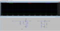
1.Used a zenner and mosfet based voltage regulator.The mosfet acting as the current buffer.
I am able to run this correctly,but the downside is that the mosfet gets insamely hot after a few minutes.The GP board where i had soldered this was also very hot.If i had left it on for some more time the lead would had started melting.")
I did a small simulation and the power loss would be around 13watt at 1 amp load.

2.Use a high wattage 15v zenner ,but the maximum i have was a 0.5w zener!
3.Searched for a wide range DCDC regulator.I found a few which are used in railway application.But they are very expensive.
4.Use a switching regulator,but most of them have a upper cuttoff voltage range of around 70v.
5.Using a voltage divider is out of question because the power rating on the resistors eed to be high!
Is there anything else i can try? Please Help
I have a high DC source , string of PV panels.My open source voltage is aroung 120-125v.When connected to load it drops to around 98-100v.
I was looking for a quick and cheap way to stepdown this voltage to around 15v,to power some circuits.The current consumption would be 800mA to 1 amp.
Here is what i have tried so far.
1.Used a zenner and mosfet based voltage regulator.The mosfet acting as the current buffer.
I am able to run this correctly,but the downside is that the mosfet gets insamely hot after a few minutes.The GP board where i had soldered this was also very hot.If i had left it on for some more time the lead would had started melting.
I did a small simulation and the power loss would be around 13watt at 1 amp load.
2.Use a high wattage 15v zenner ,but the maximum i have was a 0.5w zener!
3.Searched for a wide range DCDC regulator.I found a few which are used in railway application.But they are very expensive.
4.Use a switching regulator,but most of them have a upper cuttoff voltage range of around 70v.
5.Using a voltage divider is out of question because the power rating on the resistors eed to be high!
Is there anything else i can try? Please Help
Attachments
-
 260.1 KB Views: 5
Last edited:


