Hi All,,
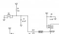
what is the difference between the following connections for MCLR PIN of PIC MCU ?

why we dont connect The MCLR directly to VDD?
what is the purpose of R,R1,C and D ?
Regards
what is the difference between the following connections for MCLR PIN of PIC MCU ?
why we dont connect The MCLR directly to VDD?
what is the purpose of R,R1,C and D ?
Regards
")