Question about behavior of L7812CV in HY1803D

Thread Starter

CarterBO

Joined Nov 10, 2024
9
Hello, this is my first post here on the forums, thanks for looking and answering.
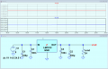
I am an electrical engineering student, and have just started studying the schematic for the HY130D for fun in my free time. What i was curious about was, the ground of the L7812 is tied to the output of the device. From what I gather, if the supply is outputting 18v, the ground to the L7812 is referenced at 18v as well. The bypass capacitor before the input is rated for 25v, with the ground voltage rising with the output too.
I am making a few assumptions, not sure if they are correct.
A scenario where the output voltage is 0 volts would imply that the voltage going into the L7812 must not exceed 25v, for risk of damaging the 330uF capacitor.
Then, if the L7812 is to supply 12v greater than ground, it can no longer linearly supply voltage past about [25-12= 13v] from the output of the HY130D.

Am I wrong about anything or everything, haha, I have assumed above? And if I am correct, how is this voltage regulator used, or useful, past about 13v?
 

Attachments

sarahMCML

Joined May 11, 2019
703
Hello, this is my first post here on the forums, thanks for looking and answering.
I am an electrical engineering student, and have just started studying the schematic for the HY130D for fun in my free time. What i was curious about was, the ground of the L7812 is tied to the output of the device. From what I gather, if the supply is outputting 18v, the ground to the L7812 is referenced at 18v as well. The bypass capacitor before the input is rated for 25v, with the ground voltage rising with the output too.
I am making a few assumptions, not sure if they are correct.
A scenario where the output voltage is 0 volts would imply that the voltage going into the L7812 must not exceed 25v, for risk of damaging the 330uF capacitor.
Then, if the L7812 is to supply 12v greater than ground, it can no longer linearly supply voltage past about [25-12= 13v] from the output of the HY130D.

Am I wrong about anything or everything, haha, I have assumed above? And if I am correct, how is this voltage regulator used, or useful, past about 13v?
The ground of the L7812 is connected to the positive output of the supply, and floats up and down with it, so never has to see the different main supply out voltage setting. Ground is NOT the main supply's negative output terminal, as far as the L7812 is concerned! It's quite a common method of supplying the internal circuitry in PSUs.
 

Thread Starter

CarterBO

Joined Nov 10, 2024
9
Hello, this is my first post here on the forums, thanks for looking and answering.
I am an electrical engineering student, and have just started studying the schematic for the HY130D for fun in my free time. What i was curious about was, the ground of the L7812 is tied to the output of the device. From what I gather, if the supply is outputting 18v, the ground to the L7812 is referenced at 18v as well. The bypass capacitor before the input is rated for 25v, with the ground voltage rising with the output too.
I am making a few assumptions, not sure if they are correct.
A scenario where the output voltage is 0 volts would imply that the voltage going into the L7812 must not exceed 25v, for risk of damaging the 330uF capacitor.
Then, if the L7812 is to supply 12v greater than ground, it can no longer linearly supply voltage past about [25-12= 13v] from the output of the HY130D.

Am I wrong about anything or everything, haha, I have assumed above? And if I am correct, how is this voltage regulator used, or useful, past about 13v?
I would like to apologize, I titled this post wrong it should reference the HY1803D. Here is the LTS asc file.
 

Attachments

Thread Starter

CarterBO

Joined Nov 10, 2024
9
The ground of the L7812 is connected to the positive output of the supply, and floats up and down with it, so never has to see the different main supply out voltage setting. Ground is NOT the main supply's negative output terminal, as far as the L7812 is concerned! It's quite a common method of supplying the internal circuitry in PSUs.
Hello sarah, Yeah it is very neat, I hadn't known about floating supplies until I looked into this for the first time. To rephrase my question though, I am aware that the L7812 never sees a different main supply output, I believe it probably sees a set amount, say 25v [total guess] from the secondary winding. The confusion lies in the fact that the output of the 7812 is in reference to what it sees at GND. And it is supposed to be 12v above GND. But the supply to the 7812, fixed at lets pretend 25v, will eventually reach an issue where the GND is floated to say 18v max, and the output can no longer be 12v above the ground float reference of 18v. It would have to reach 30v to be 12v above ground, which is physically impossible with a 25v input.
 

sarahMCML

Joined May 11, 2019
703
Hello sarah, Yeah it is very neat, I hadn't known about floating supplies until I looked into this for the first time. To rephrase my question though, I am aware that the L7812 never sees a different main supply output, I believe it probably sees a set amount, say 25v [total guess] from the secondary winding. The confusion lies in the fact that the output of the 7812 is in reference to what it sees at GND. And it is supposed to be 12v above GND. But the supply to the 7812, fixed at lets pretend 25v, will eventually reach an issue where the GND is floated to say 18v max, and the output can no longer be 12v above the ground float reference of 18v. It would have to reach 30v to be 12v above ground, which is physically impossible with a 25v input.
The L7812 is powered by a totally separate winding on the transformer (T8,T9 & T10), and the maximum voltage it ever sees is the voltage across C1. Its 0V rail, whilst being connected to the +Ve output of the main PSU has no stress on it regardless of how high the voltage gets between the two output rails of the main PSU. The PSU could be designed to supply 0 to 100 Volts for example, and the L7812 would still see exactly the same as this one.

The L7812's 0V is defined as circuit GND, and always will be. You can imagine the PSU as the negative rail moving away from GND by however many volts as you set it for, but it's purely a way of looking at it! This is not EARTH reference, which is shown by another symbol, and probably is a separate terminal on the supply. You can connect that to the either rail if you want to, it makes no difference!
 

Thread Starter

CarterBO

Joined Nov 10, 2024
9
The L7812 is powered by a totally separate winding on the transformer (T8,T9 & T10), and the maximum voltage it ever sees is the voltage across C1. Its 0V rail, whilst being connected to the +Ve output of the main PSU has no stress on it regardless of how high the voltage gets between the two output rails of the main PSU. The PSU could be designed to supply 0 to 100 Volts for example, and the L7812 would still see exactly the same as this one.

The L7812's 0V is defined as circuit GND, and always will be. You can imagine the PSU as the negative rail moving away from GND by however many volts as you set it for, but it's purely a way of looking at it! This is not EARTH reference, which is shown by another symbol, and probably is a separate terminal on the supply. You can connect that to the either rail if you want to, it makes no difference!
Hello Sarah, thank you for your response again. I think we are in agreement here mostly. Yes indeed the maximum voltage it ever sees is what occurs at C1. Yes the regulator has no stress on it regardless of how high the voltage at the output goes, as designed. Yes the L78's ground is defined as circuit ground. Consider though, if my voltage at C1 were lower than or equal to the circuit GND, what would occur? This is what I am trying to figure out. The voltage regulator would be limited to C1 at output in this case. Then what of the behavior for the rest of the circuit?
 

ericgibbs

Joined Jan 29, 2010
21,542
Hi CBO,
I misread your problem post, when you posted that LM7812 simulation I thought you had a query on that circuit.
If you are you still requiring help, please post a simple sketch, which can be more descriptive than text.

E
 

sarahMCML

Joined May 11, 2019
703
Hello Sarah, thank you for your response again. I think we are in agreement here mostly. Yes indeed the maximum voltage it ever sees is what occurs at C1. Yes the regulator has no stress on it regardless of how high the voltage at the output goes, as designed. Yes the L78's ground is defined as circuit ground. Consider though, if my voltage at C1 were lower than or equal to the circuit GND, what would occur? This is what I am trying to figure out. The voltage regulator would be limited to C1 at output in this case. Then what of the behavior for the rest of the circuit?
Sorry it's taken me so long to get back to you, been very busy today.

The voltage at C1's negative pin IS at circuit GND (by which I mean the PSU's circuit GND, which is its Positive output). It can't be anything else in this circuit. Do you mean in some other hypothetical circuit? I'm not understanding what you're after here.
 
Top