Query on using MOSFET as a switch

Thread Starter

shivashankar_p

Joined Nov 10, 2015
50
Hi,

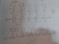
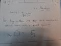
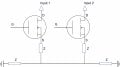
I am planning to use MOSFET as a switch. I have a series of Input Voltages, each connected to a load. And the loads are connected in a network. Here, I want each circuit to be closed only when I want it. Hence, I want to connect the load (an inductor) at the Source. please take a look at the attached image. Will this setup work?

Thanks
 

Attachments

crutschow

Joined Mar 14, 2008
34,284
The source voltage will be somewhat less than the MOSFET gate voltage minus the MOSFET Vgs threshold voltage as the transistor is acting as a source-follower.
I assume that's not what you want.

What exactly are all the voltages and currents in this circuit?
 

Thread Starter

shivashankar_p

Joined Nov 10, 2015
50
The source voltage will be the gate voltage minus the MOSFET Vgs threshold voltage.
I assume that's not what you want.

What exactly are all the voltages and currents in this circuit?
No. I don't want the voltage applied to the load to be Vgs-VT, but the Input supplied by me.
The input voltages must be in the order of several hundred millivolts & the current in a few milliamps.
 

crutschow

Joined Mar 14, 2008
34,284
No. I don't want the voltage applied to the load to be Vgs-VT, but the Input supplied by me.
The input voltages must be in the order of several hundred millivolts & the current in a few milliamps.
What is the control voltage value?
If you use a control voltage of 10V (5V for a logic-level type MOSFET) to turn it on, than the source voltage will be essentially equal to the drain (input) voltage.

What is the switching frequency?
 
Last edited:

Thread Starter

shivashankar_p

Joined Nov 10, 2015
50
Can I connect use the
What is the control voltage value?
If you use a control voltage of 10V (5V for a logic-level type MOSFET) to turn it on, than the source voltage will be essentially equal to the drain (input) voltage.

What is the switching frequency?
The switching frequency is 5kHz. I haven't decided on the gate voltage, but it will probably be 5V (in case I opt for logic-level types) or 10 V; definitely much higher than the Drain Voltage.

Under the described specifications, will the switching work seamlessly?
 

Attachments

Papabravo

Joined Feb 24, 2006
21,159
I'm not at all certain that you understand the nature of a MOSFET and how they can be used for this purpose. Part of the problem is that your schematic "fragment" is incomplete and is missing important details. I'm asking you to try to make a more complete schematic with all of the nodes in the circuit connected and symbols representing the actual components with values. The method you use for driving the gates is also important as well as the sources for Input 1 and Input 2. From that it may be possible to create a simulation so you can examine the results to see if your scheme is workable. Can you do this for me, so I can help you?
 

Thread Starter

shivashankar_p

Joined Nov 10, 2015
50
I'm not at all certain that you understand the nature of a MOSFET and how they can be used for this purpose. Part of the problem is that your schematic "fragment" is incomplete and is missing important details. I'm asking you to try to make a more complete schematic with all of the nodes in the circuit connected and symbols representing the actual components with values. The method you use for driving the gates is also important as well as the sources for Input 1 and Input 2. From that it may be possible to create a simulation so you can examine the results to see if your scheme is workable. Can you do this for me, so I can help you?
I used the MOSFETs, one p-channel and one n-channel, individually to use as a switch. When I tried to switch ON/OFF a LED, both worked excellently fine. But, when I tried to use them with a Piezoelectric-oscillator network, they don't work. I will explain with the attached diagram. There are a series of piezoelectric oscillators, and each oscillator is connected to an impedance. The impedances in-turn are connected in a network. I want to open and close the switches to the impedances. When I tried this with both the p-channel and the n-channel MOSFET, they didn't work. They just act as if the switch is open. Any ideas as to why this happens? For the case A depicted in the figure, I used the p-channel MOSFET. The n-channel for case B. The respective mosfets were STD10P6F and IRFZ46N
 

Attachments

Papabravo

Joined Feb 24, 2006
21,159
It is because you insist on using simplistic diagrams that do not properly convey the requisite information. You are either going to have to draw an informative schematic with components and values or you are going to have to solve your problem on your own. MOSFETS don't work on floating loads where the voltage level on the source pin is connected to an unknown DC voltage.
 

Thread Starter

shivashankar_p

Joined Nov 10, 2015
50
It is because you insist on using simplistic diagrams that do not properly convey the requisite information. You are either going to have to draw an informative schematic with components and values or you are going to have to solve your problem on your own. MOSFETS don't work on floating loads where the voltage level on the source pin is connected to an unknown DC voltage.
Sorry about that. I will send a clear circuit diagram shortly.
 

DC_Kid

Joined Feb 25, 2008
1,072
The schematic shows enhanced Nfets. SD is the controlled current path. Why is Z on the source side of the fet? Is the voltage like a rail-rail type, or is it basic +vcc and zero(gnd)?
 

Thread Starter

shivashankar_p

Joined Nov 10, 2015
50
It is because you insist on using simplistic diagrams that do not properly convey the requisite information. You are either going to have to draw an informative schematic with components and values or you are going to have to solve your problem on your own. MOSFETS don't work on floating loads where the voltage level on the source pin is connected to an unknown DC voltage.
Please find the informative schematic attached. I have specified all the values. The Piezoelectric crystals used to generate the input voltage are identical, and each one has a capacitance of 3.5nF. Though all the piezoelectric crystals are separated, they are grounded in a common terminal. The voltage generated by the piezo is in the order of a few mV (usually less than 10mV).

In the test, I only connected one MOSFET and used an Arduino to open and close the switch. All the other crystals were directly connected to the load Z. With the setup, the MOSFET always remained in an open condition.
 

Attachments

DC_Kid

Joined Feb 25, 2008
1,072
The drawing conflicts itself. It says "Pfet", but Nfet's are depicted.
Download a free schematic drawing tool, LTspice or something like it, use the right parts, post back.
 
Top