 Facebook
 Google
 GitHub
 Linkedin
Hello
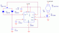
Referring to the attached schematic for a PWM DC motor controller does the +V motor label (top right) imply that the motor itself is powered by it's own supply separate from the +3-18V supply labeled above the 555 (which powers the IC).
If so, could the motor be powered by the same power supply anyway and if it were would the circuit need changing or would it indeed be redundant. I know one use of transistors is to isolate supplies from one another - put crudely I'm sure, limited knowledge, forgive me!
I simply want to vary the speed of a DC motor. From Googling I gather just using a pot to control voltage isn't the best way to do things. I'm making a zoetrope and I don't yet know the optimum speed for the motor not least of all because the drive mechanism is yet to be finalised.
Thanks
Jim
Schematic credit: http://www.dprg.org/tutorials/2005-11a/index.html
Motor details: http://proto-pic.co.uk/micro-metal-gearmotor-100-1/
Attachments
-
 5.4 KB Views: 127


