quarter wave coaxial cable operation

Thread Starter

yef smith

Joined Aug 2, 2020
717
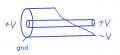
Hello,There is a basic consept of taking a coaxial cable and making a tapered cut on the outer coating thus creating balanced output from unbalanced input.,I am trying to understand how exactly this consept works.
Why quarter wavelength transformes it into balances?
Thanks.

1617276223984.png
 

Attachments

Papabravo

Joined Feb 24, 2006
21,157
A coaxial cable with the shield intact looks like a long string of L-sections with distributed series inductance per foot, and distributed capacitance per foot. In the area where the shield is cut away the inductance per foot of the wire is the same but the capacitance per foot is not there. As more of the shield surrounds the center conductor the capacitance per foot converges to the value defined by the particular coax and it's characteristic impedance. The answer to your question is in the solution to the differential equation and the boundary conditions that describe the situation.

It might also help to think in terms of:
  1. What is happening with a standing wave on this section
  2. What is happening with a traveling wave on this section
 

Thread Starter

yef smith

Joined Aug 2, 2020
717
Is there an intuition regarding why quarter wave length?
There is a quarter wave tansformer for impedances.but i am not sure if it has something to do with here?
Thanks.
 
Last edited:

Papabravo

Joined Feb 24, 2006
21,157
Is there an intuition regarding why quarter wave length?
There is a quarter wave tansformer for impedances.but i am not sure if it has something to do with here?
Thanks.
Yes, there is an impedance transformation going on. At one end you have the characteristic impedance of the coaxial cable and at the other end you have a single conductor with little or no capacitance to ground (the shield). We understand pretty well what happens at an impedance discontinuity (reflection and transmission/absorption), but what happens when the impedance changes less abruptly? The same kinds of things, but in relatively different amounts. I suspect more transmission and less reflection. I also suspect that as more grounded shield surrounds the conductor there will be less radiation.

As to the question of why a quarter wave, I believe it is because a quarter wavelength is conducive to having a standing wave at a particular frequency.

Disclaimer. I haven't done the math on this and I have not encountered this question before. Consider all of what I have said to be rooted in intuition and experience. If I have said anything inaccurate then I apologize.
 

nsaspook

Joined Aug 27, 2009
13,079
Is there an intuition regarding why quarter wave length?
There is a quarter wave tansformer for impedances.but i am not sure if it has something to do with here?
Thanks.
https://www.antenna-theory.com/definitions/balun.php

At the quarter wave length (the taper increases the bandwidth of the balun at the expense of exact impedance matching) the outer skin of the coax ground conductor is a separate conductor from the inner skin due to skin effect. With the tapered cut on the coax this means that the right -V point is not at RF ground IRT the left side of the coax GND.
balun.jpg
https://www.antenna-theory.com/definitions/taperedbalun.php
 
Last edited:

nsaspook

Joined Aug 27, 2009
13,079
Hello Nsaspook,could you please help me with the grating lobe intuition i wrote in the question bellow.
I mathematickly wrote a radiation patten from two sources i could not see how to show an expression with grating lobe based on what i developed.how should i update the expression to show the phenomena?

https://forum.allaboutcircuits.com/...ating-lobe-problem-in-broadside-array.177774/

Thanks.
It's time for you to develop your own intuition by searching, surveying and reading the published information on the subjects.
 

Thread Starter

yef smith

Joined Aug 2, 2020
717
Hello Nsaspook, i have solved it with the matlab code shown bellow,we see the grating lobes comming as distances rises.

regarding the BAULN question, is there some intuition regaring why short length increases bandwidth?
Thanks.

x=-180:0.01:180;
x_rad=(pi/180).*x;
y=cos(2*pi*x_rad);
plot(x,y)

1617312636237.png
 
Top