 Facebook
 Google
 GitHub
 Linkedin
Worksheet link: https://www.allaboutcircuits.com/worksheets/dc-branch-current-analysis/
First of all, I don't get why transistor is treated as a current source. Isn't it just a switch that lets current through depending if gate is on or off? Additionally, the question calls out two sources (two batteries) but if transistor is a source then shouldn't the text in the question talk about three sources?
If I assume that current flowing down from that junction is 5mA then it makes sense to me why we would define current from 7.2V battery as \( 5\text{mA} - I \).
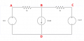
I've redrawn it into (hopefully) an equivalent circuit:

Still, I don't know how to take it from there.
When I calculate a voltage drop in 6v source(+) -> 5mA "source" -> 6v source(-) loop, 6V is being dropped so it'd seem that 6 mA has to be dropped: \[ I = \frac{6}{1000} (\frac{\text{V}}{\Omega}) = 6 \text{mA} \] but there's a 5mA source on this path and I don't know what to make of it.
I suppose I'm missing something obvious again. All suggestions welcome.
- LD
First of all, I don't get why transistor is treated as a current source. Isn't it just a switch that lets current through depending if gate is on or off? Additionally, the question calls out two sources (two batteries) but if transistor is a source then shouldn't the text in the question talk about three sources?
If I assume that current flowing down from that junction is 5mA then it makes sense to me why we would define current from 7.2V battery as \( 5\text{mA} - I \).
I've redrawn it into (hopefully) an equivalent circuit:
Still, I don't know how to take it from there.
When I calculate a voltage drop in 6v source(+) -> 5mA "source" -> 6v source(-) loop, 6V is being dropped so it'd seem that 6 mA has to be dropped: \[ I = \frac{6}{1000} (\frac{\text{V}}{\Omega}) = 6 \text{mA} \] but there's a 5mA source on this path and I don't know what to make of it.
I suppose I'm missing something obvious again. All suggestions welcome.
- LD


")


