PWM Parallel Power Transistors

SgtWookie

Joined Jul 17, 2007
22,230
And what the heck is that (battery desulphator circuit)?
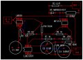
http://www.dallas.net/~jvpoll/Battery/aaDesulfatorSurvey.html

There's a message board here:
http://leadacidbatterydesulfation.yuku.com/directory
Lots of reading.
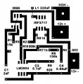
Anyway, 18 turns on one of those toroidal cores would work fine for a 1mH (1000uH) inductor. You'd be better off using an air core inductor for the 220uH, or an iron powder core rather than ferrite. Higher frequency range is the reason.

For the air core inductor, using a 1" diameter spool with end flanges spaced 0.42" apart, winding on 68 turns of AWG 16 magnet wire should work quite well.
 
Last edited:

SgtWookie

Joined Jul 17, 2007
22,230
My favorite local haunt is Skycraft Parts & Surplus:
http://www.skycraftsurplus.com/
They have an unbelievable assortment of stuff! They have all sizes of magnet wire. They couldn't hope to list everything on their site; not enough manpower.

Just E-mail them with what kind and how much you're looking for from the Contact Us page:
http://www.skycraftsurplus.com/index.asp?PAGEACTION=CONTACTUS

They have 1,000 foot spools of mil-spec AWG 24 stranded wire for $20 - for most hobbyists, that's a lifetime supply ;)
 

cat3rn

Joined Jun 3, 2008
117
The output frequency of the 555 starts off at around 14kHz; when the current reaches the preset level (right now around 22.5A), the frequency increases to approximately 24kHz.
I would like (and I am not sure I am even asking the correct question) the output to be able to handle up to 60 amps.

?????

I also attached a pic of the layout for your schematic. Do I need R3, D5 and L1 on the board or is that just part of the "fake" cell?
 

Attachments

SgtWookie

Joined Jul 17, 2007
22,230
I would like (and I am not sure I am even asking the correct question) the output to be able to handle up to 60 amps.
You wouldn't want that much current flowing through a cell, unless you had a LOT of plate area. Besides, your alternator would not likely tolerate such a heavy load very well, in addition to it's normal load. Unless you're going to add a separate alternator, plan on limiting your current to 30A or less.
I also attached a pic of the layout for your schematic. Do I need R3, D5 and L1 on the board or is that just part of the "fake" cell?
R3 and D1 through D4 are actually my guess as to what a cell looks like electrically; basically a semiconductor with resistance in series. I eliminated the capacitive portion, as the very low resistance due to the electrolyte solution relegates the capacitance to a minor parasitic rather than the major feature. So, R3, D1-D4 are replaced physically and electrically by your cell.

L1 does not have to be on the board, but why not? One less part floating around.

D5 doesn't have to be on the board either.

Your trace widths are extremely narrow. Fatten them up! Make your vias/pads much larger in diameter.

I see you've specified an LM555. It needs to be an SE555 for the correct temperature range. The part I'd linked to previously is a DIP model; if you want an SMT version, you'll need to select a different part. Same with the opamp.

As far as the opamp goes; you need to do something with the unused side to ensure it doesn't oscillate.
Connect the output to the inverting input, and the noninverting input to the noninverting input to the other noninverting input. This will create a simple voltage follower that shouldn't oscillate.
 
Last edited:

cat3rn

Joined Jun 3, 2008
117
You wouldn't want that much current flowing through a cell, unless you had a LOT of plate area. Besides, your alternator would not likely tolerate such a heavy load very well, in addition to it's normal load. Unless you're going to add a separate alternator, plan on limiting your current to 30A or less.
Will do I'll run 3 seperate PWMswitht he4 3 diff cells. BTW its a 120 amp alt.

Your trace widths are extremely narrow. Fatten them up! Make your vias/pads much larger in diameter.
That is just the circuit trace. I still have to do the layout in paintshop pro but I will make them PHAT. lol

I see you've specified an LM555. It needs to be an SE555 for the correct temperature range. The part I'd linked to previously is a DIP model; if you want an SMT version, you'll need to select a different part. Same with the opamp.
I will change that and order the SE555's. Its just the program pcb123 doesn't have the SE label. I will change it in PSP.

As far as the opamp goes; you need to do something with the unused side to ensure it doesn't oscillate.
Connect the output to the inverting input, and the noninverting input to the noninverting input to the other noninverting input. This will create a simple voltage follower that shouldn't oscillate.
Can do that. Thanks.
 

cat3rn

Joined Jun 3, 2008
117
Mind you, this is based upon my concept of what a single cell looks like electrically when under load. It may be significantly flawed. I don't have a cell to experiment with. However, I believe that a cell could be made to function reasonably close to this model by varying the concentration of the electrolyte.

If someone wants to send me a cell and dry powdered electrolyte, I'll be happy to experiment with it.
I am going to build you a cell so that you can experiment on it. It will take about 3 weeks for the funds, parts, cutting and waiting for the marine adhesive to completely dry.

It is very heavy and I will need your shipping address in order to get it to you. You can email me privately at cat3rn@hotmail.com.

I will also send you about 2 gms of K-Hydroxy in order to test it out. It will be in a separate package.

Bill
 

Audioguru

Joined Dec 20, 2007
11,248
Why not burn cheap gasoline instead of expensive valves and pistons?
Nobody has ever proved that HHO increases fuel economy except at idle when the mixture is too lean. When it is too lean then NOX is too high to pass the polution test.
 

cat3rn

Joined Jun 3, 2008
117
Why not burn cheap gasoline instead of expensive valves and pistons?
Nobody has ever proved that HHO increases fuel economy except at idle when the mixture is too lean. When it is too lean then NOX is too high to pass the polution test.

Plenty of people have already proved it. It is just a matter of believing.

Burn HOH rather than gas = water emissions.

Magnetics also run cars and trains but nobody believed them at first either.

Seek an answer to a problem rather than just complaining about it. That is my motto.

BTW what is so cheap about gas?
 
Last edited:

cat3rn

Joined Jun 3, 2008
117
Anyway, 18 turns on one of those toroidal cores would work fine for a 1mH (1000uH) inductor.
Where would I use this in the circuit?

You'd be better off using an air core inductor for the 220uH, or an iron powder core rather than ferrite. Higher frequency range is the reason.
For the air core inductor, using a 1" diameter spool with end flanges spaced 0.42" apart, winding on 68 turns of AWG 16 magnet wire should work quite well.

Would a 222nH do ok? Found it below

https://secure.coilcraft.com/forms/...OKEN=62001887&jsessionid=f630fae452c722207733


OR what would I use to build my own?
 

cat3rn

Joined Jun 3, 2008
117
As far as the opamp goes; you need to do something with the unused side to ensure it doesn't oscillate.
Connect the output to the inverting input, and the noninverting input to the noninverting input to the other noninverting input. This will create a simple voltage follower that shouldn't oscillate.
Could you show me how that would be wired?

I have also attached a pic of the circuit layout complete with the PHAT tracings. Let me know if the layout is correct?
 

Attachments

SgtWookie

Joined Jul 17, 2007
22,230
Where would I use this in the circuit? (1000uH inductor)
Where it's shown in the schematics published on the site that I've already posted.
Would a 222nH do ok? Found it below (snip)
No. 222nH = 0.222uH. You need around 220uH, or 1,000 times as much.

OR what would I use to build my own?
You need magnet wire and a form to wind it on.

Basically, a spool. You can make a spool out of almost anything.

220uH is a fairly large value of inductance. You can make a 220 uH inductor that would be suitable for this project by using a spool that was 1" in diameter with flanges 1/2 inches apart, and winding on 81 turns of AWG 20 magnet wire. That'll take about 26 feet of wire. The outside diameter of the inductor will be about 1.4".

Of course, if you're trying to use anything different than what I've specified above, your mileage will vary - and considerably.

However, if you provide dimensions of a spool that you might have available, along with what AWG size of magnet wire that you have, I could tell you how many turns that you will need.

Basically, the larger the diameter of the spool, the higher the inductance.
The smaller the distance between the flanges, the higher the inductance.
 

SgtWookie

Joined Jul 17, 2007
22,230
Will do I'll run 3 seperate PWMs with the 3 diff cells. BTW its a 120 amp alt.
Just to make sure you know, you're not going to get "over-unity" gas production (or even close) from a cell running with "brute force" electrolysis.

While minor amounts of "HHO" may improve fuel economy somewhat (any improvement is good in my book) in a vehicle with an engine that has been adapted for such purposes, there is no way that you will be able to run the engine and power the vehicle from a brute-force "electrolyzer" without external energy input.

If I thought I could do that, I would've connected a gas-powered turbine to a generator-powered "electrolyzer" and sucked all of the neighboring lakes dry.

But that's not realistic. At best, I'd get perhaps 65% back out of the power I'd put out to get the gas.

As a "fuel enhancer" for gasoline powered vehicles, you might be able to get 5% to perhaps 25% back. Your mileage will definitely vary. Of course, making such vehicle modifications bypasses many of the federally mandated emissions controls, and is therefore technically illegal. However, there has been some evidence presented that the presence of "HHO" in the combustion process actually reduces noxious emissions, so I'm letting this issue slide for the moment.

Besides, you're going to try it anyway. Might as well try to keep you from destroying your vehicle, wallet, and the environment simultaneously. ;)
 

cat3rn

Joined Jun 3, 2008
117
Just to make sure you know, you're not going to get "over-unity" gas production (or even close) from a cell running with "brute force" electrolysis.

Of course, making such vehicle modifications bypasses many of the federally mandated emissions controls, and is therefore technically illegal. However, there has been some evidence presented that the presence of "HHO" in the combustion process actually reduces noxious emissions, so I'm letting this issue slide for the moment.

Besides, you're going to try it anyway. Might as well try to keep you from destroying your vehicle, wallet, and the environment simultaneously. ;)
Ok all warnings and relative considerations are well taken. Douglas County where I live has no emission laws. Besides with all of my other mods have still passed smog checks that I have done just for giggles. Yes I am going to build it anyway. Not without any considerations about these warnings as I too don't want to be buying a new car. (My wife would kill me If I don't do it myself first. lol) or end up like the hindenburg. So all I need help with is someone to help me out withn a PWM and an EFIE. I will give all credit and partial royalties when I finish this project to those that do. I do not want any glory just a hydrogen car. It can be done with the right tools and right now you guys are the needed tools at this point. I will not throw you away when I am done. I will give credit where credit is due. You can use this post as proof. I have the cell almost completed and ready to fire up without a PWM. I will take a video and post it. I just need to get my K-Hydroxy weighed out and mixed and then connect the 12 volts. I have already built 2 more cell containers and 2 more bubblers while waiting for the K-Hydroxy. It will take another paycheck to come in order for me to order another set of SS plates to put together to get to the Sgt. but I will.
 
Top