 Facebook
 Google
 GitHub
 Linkedin
I like the Buck Boost setup very much. I am looking to build the most efficient PWM setup using easy to obtain supplies. Would it be possible to create me a circuit and a layout to print on a PCB. I would gladly become a partner with you and split the profits on a mutual agreement as I plan to mass produce these items. Not to make a great profit but to allow us to not have to depend so much on fossil fuels. I plan to get an older car (with a carb) and run it totally on Hydrogen as then I won't have to use an EFIE.
PWM Parallel Power Transistors
- Thread starter damianhealey
- Start date
Scroll to continue with content
Is there something to be done to the circuit that will accommodate the number of plates I am running? It is very difficult at this point to remove one of the plates. I can do one less neutral plate on my next setup.In order for yours to be able to work with that circuit, you may need to remove one of the intermediate plates from each +/- combination, or use something more like a buck-boost or flyback current supply.
Let's back up a step. You mentioned that you were using wire ties as plate separators. Those things are usually made out of nylon, I believe.Is there something to be done to the circuit that will accommodate the number of plates I am running? It is very difficult at this point to remove one of the plates. I can do one less neutral plate on my next setup.
Have you tested how they might stand up in a concentrated electrolyte solution under widely varying temperatures?
I tried looking them up on this page:
http://www.k-mac-plastics.net/data sheets/nylon_chemical_resistance_chart.htm
...but there was no listing for K-phos (Potassium and Sodium Phosphate).
Some months ago, on a whim I tried using a wire tie to keep a circuit board I was etching off the bottom of the etchant container; the etchant was hydrogen peroxide with muriatic acid added. To my surprise, the wire tie partially dissolved after only a few minutes in the etchant. Some of the goo from the dissolved wire tie got on the PCB I was etching, and acted as a resist for the etchant, ruining it.
I hope you ran an extended test under varying temperatures for the other materials you're using as well.
Back to the question at hand. How do you know what the voltage per individual cell will be? Did you build a single-cell prototype?
If so, try experimenting with your single-cell prototype with different strengths of electrolyte.
People who've build various versions of H2O2 cells have reported that the current through the cell increases quite a bit after they've been driving for a while. One variable is the concentration of the electrolyte; as water is removed, the electrolyte will become more concentrated. I can only assume that the more concentrated electrolyte is more conductive than the more dilute solution.
Another variable is temperature. Frankly, I have no idea how much effect the temperature of the electrolyte solution or the cell has on it's conductivity or breakdown voltage.
But if you have a single test cell, this would be a really worthwhile experiment. After all, your goal is optimal gas production, right? Without such test data from a small cell that's easily driven from relatively inexpensive equipment, you'll be spending a lot of time and money building different versions of current controllers/buck/boost/DC-DC-converters. It would be much less risky to experiment with a single cell.
As far as gas production, there is a point at which applying more current produces minimally more gas, while causing considerably more heating of the electrolyte. You really want to stay below that point, otherwise your power is being wasted. Not having experimented with this personally, I do not know how quickly this transition occurs, or under what conditions; temperature, electrolyte used, concentration of electrolyte, plate material, plate separation, plate dimensions, etc.
But too many variables will make the test series overly complicated. Complicating things is not the goal.
Gas production vs thermal rise (°C/sec) vs current vs voltage (across cell) vs cell temp@start vs electrolyte concentration.
That's already a considerable number of variables. It'll be tough to capture the data without some kind of automation, like a microcontroller equipped with sensors. The sensors don't have to be complex. A couple of thermistors could be used to monitor temperatures at the top and bottom of the cell. Current through the cell could be directly measured as a voltage drop across a precision non-inductive power resistor. Voltage across the cell could be directly measured by a uC (microcontroller). An inverted water-filled 1L soda bottle could be used as a positive-displacement gas flow meter; when all of the water has been displaced by the gas, the test is ended.
Without such baseline data, you'll be flying blind. It's much cheaper to crash a kite than a 747.
Once you narrow in on the range of parameters that look the most promising, you could add plate spacing as another variable.
I guess I forgot to mention that that will be pulled out after the marine adhesive is dry. If you look up marine adhesive it work very well in harsh environments. High electrolyte content like pyramid lake in Reno NV is a prime example. If it can withstand that then there is no problem inside a cell.Let's back up a step. You mentioned that you were using wire ties as plate separators. Those things are usually made out of nylon, I believe.
That one is just simple math. At 14 volts (normal voltage produced by an alternator) with 6 plates it would be approx 2.333333v per plate. Going between each positive and negative plate. Other individuals have already run multiple tests using this design. The voltage stays pretty much the same but the amperage changes (albeit very little) as heat is higher or lower.Back to the question at hand. How do you know what the voltage per individual cell will be? Did you build a single-cell prototype?
The different strengths of potassium hydroxide (sorry not K-phos) also changes the amperage. (This changes it much more than the heat) Higher concentrate = more amps needed. That's was the reason for the IRFP064N power MOSFET it is rated at 110 amps.If so, try experimenting with your single-cell prototype with different strengths of electrolyte.
That is the reason for the current sensing PWM. I want it to be able to adapt to the current needed. I also have sensors that will be in place to let me know when I get below a certain amount of water (w/ the electrolyte) and can add more at the touch of a button to make the concentration remain about the same. Using the 10 gms K-Hydroxy it is about a 1:1 exchange. 10 gms = 10 amps needed.People who've build various versions of H2O2 cells have reported that the current through the cell increases quite a bit after they've been driving for a while. One variable is the concentration of the electrolyte; as water is removed, the electrolyte will become more concentrated. I can only assume that the more concentrated electrolyte is more conductive than the more dilute solution.
Other people that have this cell design have already run those tests. Besides mine will be sitting in the trunk to decrease the engine heat. Also if needed I can use a small transmission cooler and wrap the lines around the ABS to provide additional cooling if needed. I can also use multiple small peltiers to cool down the cell. There are many ways to maintain a certain temperature so that variable is pretty much eliminated.Another variable is temperature. Frankly, I have no idea how much effect the temperature of the electrolyte solution or the cell has on it's conductivity or breakdown voltage.
Way too expensive for me to set up. Besides most of the variables won't have the effect that you are stating or have already been studied or controlled.But too many variables will make the test series overly complicated. Complicating things is not the goal.
That's already a considerable number of variables. It'll be tough to capture the data without some kind of automation, like a microcontroller equipped .
'Buck' regulators can be quite efficient, some are up to 97% under certain conditions. The circuit I put up probably does not even approach that; yet it would be far better than the original circuit. Buck-boost regulators are more complex, and are generally less efficient. There's an extra diode in the circuit that causes additional power dissipation (waste). There is no "free lunch" in electronics.I like the Buck Boost setup very much.
Well, those parameters are not quite mutually exclusive, but there are always a number of trade-offs that have to be considered. There are several problematic items in this project, not the least of which is the operating temperature range. Going back to the original poster's circuit, an LM324N was specified in the original schematic. While the opamp is widely available and inexpensive, the operating temperature range of 0°C to 70°C alone disqualifies it from serious consideration. A minimum acceptable range would be -40°C to 125°C.I am looking to build the most efficient PWM setup using easy to obtain supplies.
Integration level is another item. There are controllers out there designed to do such things, but the problem with settling on a particular controller design is obsolescence. Newer, more efficient designs are constantly being introduced, and the older designs are discontinued. The newer designs tend to be more expensive.
This application (H2O2 cells in general), being somewhat unique, really should be microcontroller based. uC's can help greatly to reduce parts count. Many of the items needed are already on board. With a simple buck or buck/boost regulator, all you can do is control current or voltage output. A uC could perform that task while monitoring other parameters, such as cell temp, electrolyte level, gas production, etc. and even communicate with the operator via a display panel.
You can even do this yourself.Would it be possible to create me a circuit and a layout to print on a PCB.
")
http://www.cadsoft.de/
At the above link is a link to download the freeware version of the Eagle Layout Editor. A tutorial is available on that page also.
Here's another tutorial on Eagle that's pretty good:
http://www.sparkfun.com/commerce/tutorial_info.php?tutorials_id=57&sipp=1&page=8
That's basically the start of a whole project, but is worth reading through.
If you want to skip the project development and get right to the Eagle tutorial, click here:
http://www.sparkfun.com/commerce/tutorial_info.php?tutorials_id=108
You'll have to get a pretty old car then - probably pre-1978.I plan to get an older car (with a carb) and run it totally on Hydrogen as then I won't have to use an EFIE.
As far as running a vehicle completely on H2O2 - that's not going to happen without using a large source of external power.
Hydrogen is not an energy creator or energy source, it's an energy carrier. Unfortunately, it takes a good bit more energy to split H2O molecules apart from each other than you get back when they are recombined during combustion. Internal combustion engines are notoriously inefficient. If you're getting 30% efficiency, it's a really good day. I basically went through all this on another thread.
OK, that makes sense. But does pyramid lake in Reno have the same chemical composition and approximate concentration that your electrolyte does?I guess I forgot to mention that that will be pulled out after the marine adhesive is dry. If you look up marine adhesive it work very well in harsh environments. High electrolyte content like pyramid lake in Reno NV is a prime example. If it can withstand that then there is no problem inside a cell.
On 2.3v/cell:
Well, the voltage produced by the alternator stays pretty much the same (roughly 13.6v to 14.5v).That one is just simple math. At 14 volts (normal voltage produced by an alternator) with 6 plates it would be approx 2.333333v per plate. Going between each positive and negative plate. Other individuals have already run multiple tests using this design. The voltage stays pretty much the same but the amperage changes (albeit very little) as heat is higher or lower
But as I've suggested a number of times in this thread, an individual cell acts more or less like a semiconductor diode. from 0v to the cell's Vf (forward voltage), the current increases minimally for the increase in voltage. After the Vf is reached, it requires a relatively large increase in current to increase the voltage drop across the cell. Increasing the concentration of the electrolyte changes the electrical characteristics of the cell, much like replacing a standard silicon diode with a Schottky rectifier.
So as your electrolyte becomes more concentrated, your cell's Vf drops, with a corresponding increase in current as the electrical system attempts to maintain the Vf across the cells.
The immediate solution (sic) to your current problem would seem to be to increase the concentration of the electrolyte solution in order to get the sum of the cell's Vf low enough so that a reasonably cost-effective buck regulator can be used.
Higher concentrate = lower Vf, which implies that current regulation is needed. Using double or more specs for the expected voltage/current in a circuit is a good practice.The different strengths of potassium hydroxide (sorry not K-phos) also changes the amperage. (This changes it much more than the heat) Higher concentrate = more amps needed. That's was the reason for the IRFP064N power MOSFET it is rated at 110 amps.
Why not simply automate the refill process? Keeping the electrolyte level constant, and at a constant dilution, is very important for consistent performance.I also have sensors that will be in place to let me know when I get below a certain amount of water (w/ the electrolyte) and can add more at the touch of a button to make the concentration remain about the same.
That is really not enough information - is that in your specific cell?Using the 10 gms K-Hydroxy it is about a 1:1 exchange. 10 gms = 10 amps needed.
Plate area alone would radically change those numbers. What's the cell Vf? Or is that wth 14V applied across it?
Did they publish data? I'm not trying to give you a hard time here; I'm trying to find out some facts.Other people that have this cell design have already run those tests.
I hope that you plan on providing a good deal of forced ventilation for your trunk. Otherwise, any leaks at all in your system will eventually result in your vehicle becoming a very rapidly expanding fireball. I'm not kidding.Besides mine will be sitting in the trunk to decrease the engine heat.
This is late in the thread, but it is possible to make the setup a bit safer. The hydrogen comes off of the cathode plates. If the electrolysis cell is built so the anode plates are in one section and the cathodes in another, with a electrolyte channel conducting current between them, then the oxygen can be vented to the air.
That means that the hydrogen feed to the engine is almost intrinsically safe - no explosion danger until it gets mixed with atmospheric oxygen in the intake manifold. Notice that the Hindenburg burned, rather than exploded.
That also means you're simply adding a fuel component, so the ECU might respond better.
Ok lets stick with the buck regulator. Can you change your circuit to get it close to as efficient as poss? Do you take PayPal as I am willing to help out a little financially for the assistance. I realize there is no fre lnch in electronics doesn't necessarily apply to your time involved but the energy put in to what you get out. However, I am not rich by any means but am willing to pay for your time as there are no electronics wizards in my area.'Buck' regulators can be quite efficient, some are up to 97% under certain conditions. The circuit I put up probably does not even approach that; yet it would be far better than the original circuit. There is no "free lunch" in electronics.
I am planning to change it to the 555 circuit you mentioned so as for now the LM324N is gone. I will go with your circuit since you think it will work for my needs better. Although the opinion might be a little biased what you are saying makes a lot of sense. I am not an electronics wizard and am just getting started learning about circuits. Thanks for all the links earlier and in other forums.Well, those parameters are not quite mutually exclusive, but there are always a number of trade-offs that have to be considered. There are several problematic items in this project, not the least of which is the operating temperature range. Going back to the original poster's circuit, an LM324N was specified in the original schematic. While the opamp is widely available and inexpensive, the operating temperature range of 0°C to 70°C alone disqualifies it from serious consideration. A minimum acceptable range would be -40°C to 125°C.
Lets just try to use what is available at the moment.Newer, more efficient designs are constantly being introduced, and the older designs are discontinued. The newer designs tend to be more expensive.
What is a uC as I am new to this sort of stuff. I am a fast learner though. IQ about 140 not bragging but most of my knowledge is in medicine not electronics.This application (H2O2 cells in general), being somewhat unique, really should be microcontroller based. uC's can help greatly to reduce parts count. Many of the items needed are already on board. With a simple buck or buck/boost regulator, all you can do is control current or voltage output. A uC could perform that task while monitoring other parameters, such as cell temp, electrolyte level, gas production, etc. and even communicate with the operator via a display panel.
I use a program called pcb123 its much easier for me to use.You can even do this yourself.
http://www.cadsoft.de/
At the above link is a link to download the freeware version of the Eagle Layout Editor. A tutorial is available on that page also.
However, I cannot create the circuits myself. I am not that knowlegable about this stuff. I use pcb123 to map others circuits out then convert it to a layout (hopefully in the correct format) then size it using a computer program to print it out to place on my copper clad material.
It will actually be a 1981 Mazda RX-7 rotary engine car.You'll have to get a pretty old car then - probably pre-1978.
If I can get 3 HHO cells to produce 2 l/m each for a total of 6 l/m that is all I will need to completely run a 6, 8 or rotary engine completely on Hydrogen. Then running engine will produce the needed energy for the cells. Ok maybe I shouldn't use the word completely.As far as running a vehicle completely on H2O2 - that's not going to happen without using a large source of external power.
Point taken but I still want to try to approach the HHO production to make it as efficient as poss.Hydrogen is not an energy creator or energy source, it's an energy carrier. Unfortunately, it takes a good bit more energy to split H2O molecules apart from each other than you get back when they are recombined during combustion. Internal combustion engines are notoriously inefficient. If you're getting 30% efficiency, it's a really good day. I basically went through all this on another thread.
I can try to experiment using that idea but I can tell you just looking into that before that it is much much less effecient when the plates are farther apart.This is late in the thread, but it is possible to make the setup a bit safer. The hydrogen comes off of the cathode plates. If the electrolysis cell is built so the anode plates are in one section and the cathodes in another, with a electrolyte channel conducting current between them, then the oxygen can be vented to the air.
That means that the hydrogen feed to the engine is almost intrinsically safe - no explosion danger until it gets mixed with atmospheric oxygen in the intake manifold. Notice that the Hindenburg burned, rather than exploded.
That also means you're simply adding a fuel component, so the ECU might respond better.
pos cell this side neg cell this side - = plate
+ = plate | | |
| + | - |
| + | - |
| + | - |
| + | - |
| + | - |
| + | - |
|______________|
Split the chambers at the top just below water line and then seperate the gases. etc etc etc
Just giving you a hand with the CODE /CODE blocks; they (somewhat) retain your formatting.I can try to experiment using that idea but I can tell you just looking into that before that it is much much less effecient when the plates are farther apart.
Split the chambers at the top just below water line and then seperate the gases. etc etc etcRich (BB code):pos cell this side neg cell this side + = plate | | | - = plate | + | - | | + | - | | + | - | | + | - | | + | - | | + | - | |_____________________|
Pyramid lake is much more caustic. Just look at a tube of marine adhesive to see what it will stand up to. It is the best stuff out there right now.OK, that makes sense. But does pyramid lake in Reno have the same chemical composition and approximate concentration that your electrolyte does?
I could do that but I would need some way to control the voltage/current so as not to blow it up. If I would have used 20gms K-Hydrox the cell would hve pulled about 20 amps form the source. The cell produces great right now with 10gms k-hyd and only 14 v using about 7 to 10 amps.On 2.3v/cell:
Well, the voltage produced by the alternator stays pretty much the same (roughly 13.6v to 14.5v).
But as I've suggested a number of times in this thread, an individual cell acts more or less like a semiconductor diode. from 0v to the cell's Vf (forward voltage), the current increases minimally for the increase in voltage. After the Vf is reached, it requires a relatively large increase in current to increase the voltage drop across the cell. Increasing the concentration of the electrolyte changes the electrical characteristics of the cell, much like replacing a standard silicon diode with a Schottky rectifier.
So as your electrolyte becomes more concentrated, your cell's Vf drops, with a corresponding increase in current as the electrical system attempts to maintain the Vf across the cells.
The immediate solution (sic) to your current problem would seem to be to increase the concentration of the electrolyte solution in order to get the sum of the cell's Vf low enough so that a reasonably cost-effective buck regulator can be used.
Higher concentrate = lower Vf, which implies that current regulation is needed. Using double or more specs for the expected voltage/current in a circuit is a good practice.
I will work on getting this done also. Maybe another adjacent tank (without any electricty attached to it) with check valves or something like that.Why not simply automate the refill process? Keeping the electrolyte level constant, and at a constant dilution, is very important for consistent performance.
Yes my cellThat is really not enough information - is that in your specific cell?
YesPlate area alone would radically change those numbers. What's the cell Vf? Or is that wth 14V applied across it?
I got the original idea from www.alt-nrg.org but am finding it not to be very efficient. Although he is selling his PWMs now. 250 a pop. I have been working on my own version for about a year now - combining ideas from a lot of people. Your idea of the microcontroller and/or the buck regulator seems to have a lot of promise.Did they publish data? I'm not trying to give you a hard time here; I'm trying to find out some facts.
His published data is on http://www.youtube.com/zerofossilfuel
Simple answer is yes. Long answer is if I can keep it cool enough I may move it to theengine area and put a heat shield around the part facing the engine. Maybe out front near the intake of the air dam.I hope that you plan on providing a good deal of forced ventilation for your trunk. Otherwise, any leaks at all in your system will eventually result in your vehicle becoming a very rapidly expanding fireball. I'm not kidding.
Just giving you a hand with the CODE /CODE blocks; they (somewhat) retain your formatting.
Thanks I couldn't find my picture of the process.
Found it.Just giving you a hand with the CODE /CODE blocks; they (somewhat) retain your formatting.

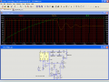
OK, here's the next iteration; one SE555N timer (for the temp range and DIP configuration) and a single opamp, with supporting resistors/capacitors of course. Nothing's finalized; just an interim circuit - a waypoint, if you will. The first is a graphic of the circuit with output, the 2nd is a Linear Technology's LTSpice compatible source file; the simulator is available as a free download from their website.
It's somewhat interesting because it uses a single 555 timer as a voltage controlled PWM.
My concept of what a single cell might look like electrically is represented by R3 and D1 through D4.
When the control voltage (pin 5) is decreased (the brown trace; scale on left), the output frequency of the 555 increases, along with the ON-time decreasing porportionate to the OFF time (gate signal, red trace; scale on left).
This causes the current going through L1 (green trace; scale on right) to stabilize at the current level established by (pot) R9. The current sense resistor R4 has a voltage drop across it porportional to the current flowing through it. C4 is charged via R7 to establish a relatively stable reference voltage.
When the voltage on C4 (also on the inverting input of the opamp) exceeds the voltage on the noninverting input, the output of the opamp decreases, which decreases the ON-time of the 555 timer's output, thus decreasing the average current in L1 and the load.
The output frequency of the 555 starts off at around 14kHz; when the current reaches the preset level (right now around 22.5A), the frequency increases to approximately 24kHz.
Mind you, this is based upon my concept of what a single cell looks like electrically when under load. It may be significantly flawed. I don't have a cell to experiment with. However, I believe that a cell could be made to function reasonably close to this model by varying the concentration of the electrolyte.
If someone wants to send me a cell and dry powdered electrolyte, I'll be happy to experiment with it.
Attachments
-
3.9 KB Views: 49
-
 72.7 KB Views: 115
It would be a little while to send you a duplicate of my cell because the SS for all of the plates is over 100.00 for the 316L grade. Any plastic container could be used for the testing.OK, here's the next iteration; one SE555N timer (for the temp range and DIP configuration) and a single opamp, with supporting resistors/capacitors of course. Nothing's finalized; just an interim circuit - a waypoint, if you will. The first is a graphic of the circuit with output, the 2nd is a Linear Technology's LTSpice compatible source file; the simulator is available as a free download from their website.
It's somewhat interesting because it uses a single 555 timer as a voltage controlled PWM.
................................
Mind you, this is based upon my concept of what a single cell looks like electrically when under load. It may be significantly flawed. I don't have a cell to experiment with. However, I believe that a cell could be made to function reasonably close to this model by varying the concentration of the electrolyte.
If someone wants to send me a cell and dry powdered electrolyte, I'll be happy to experiment with it.
The K-hyd can be obtained at www.snowdriftfarms.com for about 20 bucks. It has to be shipped UPS ground secondary tot he bio-hazardability of it. Oh look I created a new word - I think. lol
I will put up a video of my cell when it is done and working even without the PWM or buck just to show the flow of HHO and approx liter per min calculated.
Last edited:
You could just go ahead and build the circuit I posted above to try out. You can buy ALL of the components for less than I could buy a couple LBS of K-hyd for. Instructions for procuring/winding the toroidal inductor are here:
http://forum.allaboutcircuits.com/showpost.php?p=91085&postcount=19
You'll need an SE555 timer, less than a buck from Digikey or Mouser.
You could use an LM2904 dual opamp instead of the LT1007; that's an automotive temp range dual opamp with input sense down to v-; it might require a bit of tweaking with R10 though - it'll probably need to be a 500K or 1 MEG pot instead of 100K.
You must order 5 or more because they have a $10.00 min order.Here's a better option for that inductor.
Go to this page:
https://www.amidoncorp.com/items/21
and order one FT-114-J. This is a J-material ferrite toroid that is under 1.2" in diameter, and is an excellent candidate for this project. It has an AL of 3170; L(mH) = AL x #turns x #turns / 1,000,000
I just ordered them if anybody wants only 1. I can get it to you for just my cost plus shipping.
Digikey has 5 pages of them - is there a specific one that would be correct?You could just go ahead and build the circuit I posted above to try out. You can buy ALL of the components for less than I could buy a couple LBS of K-hyd for. Instructions for procuring/winding the toroidal inductor are here:
http://forum.allaboutcircuits.com/showpost.php?p=91085&postcount=19
You'll need an SE555 timer, less than a buck from Digikey or Mouser.
You could use an LM2904 dual opamp instead of the LT1007; that's an automotive temp range dual opamp with input sense down to v-; it might require a bit of tweaking with R10 though - it'll probably need to be a 500K or 1 MEG pot instead of 100K.
And what the heck is that (battery desulphator circuit)?Oops, sorry about that - I've never ordered from them before, but lots of hobbyists have.
But actually, you could use a couple of the others to build a battery desulphator circuit; they would work just fine.
As I said I am very new to this electrical stuff. But I am learning a lot from you guys.
Last edited:


