 Facebook
 Google
 GitHub
 Linkedin
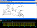
I want to add a second power transistor to a PWM with the objective of reducing the power dissipation and hopefully heat generated. Can somebody tell me the best way to add a second transistor?
The circuit can be found at http://alt-nrg.org/ click on the Plans & Schematics link and then My newest current sensing PWM-v2:
Thanks in advance,
Damian
The circuit can be found at http://alt-nrg.org/ click on the Plans & Schematics link and then My newest current sensing PWM-v2:
Thanks in advance,
Damian

")


