PWM modulate 12V with MOSFET

Thread Starter

Linbaato

Joined Oct 12, 2021
15
Hello together,

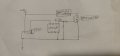
I want to dim an LED strip (12V / 4.5A) by PWM modulating (I hope that is the correct term) a 12V Power supply. I want to generate the PWM signal with an Attiny that is powered by the same supply. The PWM signal will be 1000Hz. If that induces too noticeable flickering for me I will try to increase that frequency a bit.

I found similar posts and informed myself about MOSFETs, but as a beginner I did not understand everything and am unsure about my setup. The choice of MOSFET went something like this: search nearby provider for TO-220(AB) one that has a max Ugs(th) of 4V or below and which RDS(on) value is under 30 Ohm. If I understood correctly my choice of 14 Ohm (@10v) might be even better since I don't switch with a high frequency. Even though I cannot find the RDS(on) value for 5V to really make this assumption.

Could you tell me if you notice anything that might not work at all or could be improved?
One thing I believe ist that I need some capacitors somewhere, maybe an electrolytic one in front of the load? Maybe a small one in front of the microcontroller?

If you additionally have any explanations or pointers as to why I'd deeply appreciate it!

Sorry for my handdrawn stuff. I don't know any better :D
 

Attachments

DickCappels

Joined Aug 21, 2008
10,661
You will probably not be happy with the dim LEDs if your RDS(on) is really 30 ohms. Figure the voltage drop across that resistance. Did you mean 30 milliohms? That would work very well.
 

Thread Starter

Linbaato

Joined Oct 12, 2021
15
You will probably not be happy with the dim LEDs if your RDS(on) is really 30 ohms. Figure the voltage drop across that resistance. Did you mean 30 milliohms? That would work very well.
Oh, yes I meant milliohms. Thanks for your input!
And I just noticed I forgot to write any resistor values or even asked about them.

Would 10kOhms for the "pin-to-gate"-resistor and 100kOhms for the pull-down-resistor work well?
 

DickCappels

Joined Aug 21, 2008
10,661
(Some text removed for clarity)
Would 10kOhms for the "pin-to-gate"-resistor and 100kOhms for the pull-down-resistor work well?
The pin-to-gate resistor might give you switching time problems (mainly power dissipation), it depends upon your PWM frequency. I think you should choose it to limit the peak output current of your PWM driver to a safe level, regardless of the gate capacitance.

The 100k should be fine, and anything between that and 1k should also be fine if the gate leads are not long enough or interference sources are not high enough to cause interference with the PWM signal.
 

Thread Starter

Linbaato

Joined Oct 12, 2021
15
The pin-to-age resistor might give you switching time problems (mainly power dissipation), it depends upon your PWM frequency. I think you should choose it to limit the peak output current of your PWM driver to a safe level, regardless of the gate capacitance.
That makes sense. So I will go with 500mOhm just to assure the pin does not source/drain more than 10mA.
 

Thread Starter

Linbaato

Joined Oct 12, 2021
15
@peterdeco @DickCappels
Has one of you a hint for me on the capacitors that might be helpful/needed?

The power supply is being used by other loads, too if that makes an influence.

If you think none will be alright that would also be a helpful tip to for me :)
 

Ian0

Joined Aug 7, 2020
13,097
The pin-to-gate resistor might give you switching time problems (mainly power dissipation), it depends upon your PWM frequency. I think you should choose it to limit the peak output current of your PWM driver to a safe level, regardless of the gate capacitance.

The 100k should be fine, and anything between that and 1k should also be fine if the gate leads are not long enough or interference sources are not high enough to cause interference with the PWM signal.
The MOSFET needs a resistance of around 10Ω to 50Ω on the gate to prevent high frequency oscillation.
The output of the ATMEGA will be about that, so it is possible that you might not need any gate resistors, but 22Ω won't go amiss.
Look for a "LOGIC LEVEL" MOSFET - the IRLZ44 would be a good choice as @peterdeco says. It's called LOGIC LEVEL for a reason! And you're driving it from LOGIC!

It's never a bad idea to include a flyback diode across the load. It's not an inductive load like a relay, but there's always inductance somewhere!
A diode between the 12V input and the 78L05 is a good idea. You'll thank me for suggesting that the first time you connect the input backwards.
 

DickCappels

Joined Aug 21, 2008
10,661
It is suggested that you follow the bypass capacitor recommendations of the manufacturer or the 78L05. Also, as close as you can get it, place a .01 uf ceramic capacitor with a 1 uf or larger capacitor across it between ATTNY85 pins 8 and 4. If you can get this all close together, the .01 in parallel with the 1 uf (or larger) can act as the output capacitor on the 78L05.
 

crutschow

Joined Mar 14, 2008
38,331
What's the advantages to my choice and your first mention of IRLZ44N?
As noted, you need a logic-level type MOSFET for a 5V drive signal to fully turn it on.
They typically have a max Vgs(th) of 2V or less.

Remember that Vgs(th) is the voltage where a MOSFET just barely starts to turn on.
You need more than 1V over the IRFZ48 max Vgs(th) of 4V to get a low on-resistance.
As shown below from the IRFZ48 data sheet, it requires a Vgs of 10V for the lowest on-resistance.

1648302232767.png
 

bassbindevil

Joined Jan 23, 2014
918
I'm just going to point out that there are PWM speed controller modules available for a couple of bucks from your favourite overseas vendors that work well as LED dimmers. (555, MOSFET, pot with switch ready to panel mount)
And another thought: switching at 1000 Hz shouldn't flicker, but such a load could possibly produce an audible tone from power supply inductors.
 
Top