PWM for MOSFET without using any IC

Thread Starter

Kutty simba

Joined May 6, 2020
7
Hi There,
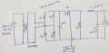
i'm a beginner and thought of designing a driver circuit for a MOSFET without using any ICs. Please give your valuable inputs to complete the task.
i will impliment your ideas and will discuss further.
 

Delta Prime

Joined Nov 15, 2019
1,311
MOSFETs exhibit three regions of operation viz., Cut-off, Linear or Ohmic and Saturation. Among these, when MOSFETs are to be used as amplifiers, they are required to be operated in their ohmic region wherein the current through the device increases with an increase in the applied voltage
the other hand, when the mosfets are required to function as switches, they should be biased in such a way that they alter between cut-off and saturation states. This is because, in cut-off region, there is no current flow through the device while in saturation region there will be a constant amount of current flowing through the device, just mimicking the behaviour of an open and closed switch, respectively. This functionality of MOSFETs is exploited in many electronic circuits as they offer higher switching rates when compared to BJTs
I would try the mosfet using it as a switch,then try Pwm
 

danadak

Joined Mar 10, 2018
4,057
A few more details needed -

1) Why no IC, you want to do discrete transistor design to learn ?
2) PWM, how are you going to control it ?
3) PWM frequency ?
4) What is the MOSFET driving ?
5) Single MOSFET or an H-Bridge you are trying to control ?
6) MOSFET load, current and voltage values ?
7) PWM logic operating at 3.3V or 5V ?

Regards, Dana.
 

jpanhalt

Joined Jan 18, 2008
11,087
Since you are asking how to design, not build, you can start here: http://www.4qdtec.com/pwm-01.html
Scroll to the bottom for more links. It's 6 parts.

Then you need to design an oscillator using discrete parts. You might search on "voltage controlled" oscillator or VCO. One approach might be to use the internakls of a old battery-operated clock (http://www.electro-tech-online.com/threads/generating-1hz-frequency.145024/#post-1225004 ). That will probably have an IC, however. For something without an IC, you can start here: http://zpostbox.ru/relax_e.htm

There is also a component-built sinewave oscillator here: https://www.electro-tech-online.com/threads/for-a-better-sine-wave.152605/#post-1313052 (post #15).

Anything you find in current hits will probably use an IC, including the NE555 or other inverters.
 

Thread Starter

Kutty simba

Joined May 6, 2020
7
MOSFETs exhibit three regions of operation viz., Cut-off, Linear or Ohmic and Saturation. Among these, when MOSFETs are to be used as amplifiers, they are required to be operated in their ohmic region wherein the current through the device increases with an increase in the applied voltage
the other hand, when the mosfets are required to function as switches, they should be biased in such a way that they alter between cut-off and saturation states. This is because, in cut-off region, there is no current flow through the device while in saturation region there will be a constant amount of current flowing through the device, just mimicking the behaviour of an open and closed switch, respectively. This functionality of MOSFETs is exploited in many electronic circuits as they offer higher switching rates when compared to BJTs
I would try the mosfet using it as a switch,then try Pwm
Thanks for the comment,
I like to use the MOSFET as a switch.
 

Thread Starter

Kutty simba

Joined May 6, 2020
7
A few more details needed -

1) Why no IC, you want to do discrete transistor design to learn ?
2) PWM, how are you going to control it ?
3) PWM frequency ?
4) What is the MOSFET driving ?
5) Single MOSFET or an H-Bridge you are trying to control ?
6) MOSFET load, current and voltage values ?
7) PWM logic operating at 3.3V or 5V ?

Regards, Dana.
Dana,
The answers are as below
1.I can't able to understand the circuit which is inside the ICs. So, i thought of doing it with discrete components.
2.I have no idea about the control
3.22KHz
4.It is driving a BLDC,24V,1.7A,41W
5.Single MOSFET
6.i used load parameters for MOSFET selection.Is the procedure correct?
7.Sorry, not yet decided(i have no idea about the voltage requirement)
 

ci139

Joined Jul 11, 2016
1,970
the collector/drain load circuits tend to become oscillating - you can use the feature to further provoke them to that -- although the oscillations may stop at very low or very high loads -- output voltage tends to be also more load dependent than in some SMPS ...
. . . or use a feedback transformer or other FBK network ??? - lot of experimenting - no good results guranteed
 

dendad

Joined Feb 20, 2016
4,635
You could use a 555 timer PWM circuit, and one of these "discrete 555" timer kits..
https://cdn.evilmadscientist.com/KitInstrux/555/555_datasheet_rev30d.pdf
There is a circuit included so a through hole version could be made on perf board without the kit if you prefer.
Or just have a real good look at the kit to figure out how it works. Then, after you do that, use an actual 555.
If you must use discrete, research how the PWM is generated, starting with a saw tooth oscillator feeding a comparator whose output will go to a FET.
But for your real power supply application, I would advised to get a specialized power supply controller chip. It will save a lot of tears.
 

jpanhalt

Joined Jan 18, 2008
11,087
You could use a 555 timer PWM circuit, and one of these "discrete 555" timer kits..
https://cdn.evilmadscientist.com/KitInstrux/555/555_datasheet_rev30d.pdf
There is a circuit included so a through hole version could be made on perf board without the kit if you prefer.
Or just have a real good look at the kit to figure out how it works. Then, after you do that, use an actual 555.
If you must use discrete, research how the PWM is generated, starting with a saw tooth oscillator feeding a comparator whose output will go to a FET.
But for your real power supply application, I would advised to get a specialized power supply controller chip. It will save a lot of tears.
None of us would have any problem suggesting a solution using an IC. Not using an IC was a specific requirement of the TS.
 

Janis59

Joined Aug 21, 2017
1,894
I can immagine ONLY one fictious case when there is ANY benefit avoid the IC. That is when work frequency is hardly over the 3 MHz. Then one of all times most brilliant ideas I had read about and even tried to alter but not very successfully, is to organize the Wilsson current mirror charging up a capacitor, on which comparator is measuring the voltage in small pseudo-linear part of graph. When comparator decides cap is "full" it makes a command to short-circuit it by separate transistor, and when other comparator decides the minimum is gained, the shortcircuiting is stopped and charging up is renewed. Thus we get a damn fast ultra-linear saw-teeth generator what voltage may be comparated with some reference voltage, thus voltage relations transporting to time-kingdom relations, including even the correct time gaps for otput bridge through-blow prevention. In the end stays ultrafast gate booster and bridge. However my aim was to get a 3...4 MHz only, thus the generator goes 6...8 MHz then comparators to get accuracy of Duty Cycle at least 5% of maximum possible, must be so fast as 8MHz=100 nanoseconds multiply to 5%= 5 ns (what already is grand problem if only one not want to suicide into emitter-bound (bipolar line) logics. But then the greatest surprize is still affront - the output transistors then must be able to deliver at least 5...10% accuracy at dU/dt of opening otherhow it will melt even on best ever possible heatsink. So dU/dt= 5 ns * 5%=0,25 ns for 600-1200 Volts and 60-100 Amperes !!! And gate driver must to assure such fantastic speed at some 30-60 Amperes into gate. My standpoint - even so small as 3 MHz not allow precision PWM at today stae of the art component level. Probably next century we shall get it. Analog solutions seems far more appropriate for this aim.
 

Janis59

Joined Aug 21, 2017
1,894
RE: Dendad - 555 kit firstly, have low accuracy but most important, cant work over 1,5 MHz (more realistic 1 MHz). There are only few methods how to get any near 3 MHz and no solutions over (however I noted one article about 6 MHz but hiding how it is realized). By the way, the close relative to famous 494 is 594 having two wonderful accuracy-advanced pwm channels be used for CV and CC aim, however it is sooooo slow - http://www.ti.com/lit/ds/symlink/tl594.pdf?ts=1588839803704
 
Last edited by a moderator:

Thread Starter

Kutty simba

Joined May 6, 2020
7
If the motor is a 2-wire type with internal commutation electronics you should be ok, but your circuit is unsuitable for the common 3-wire type of motor requiring multi-phase inputs for correct commutation.
You are a keen observer! Motor is having 4 wires(Positive, Nagative, Tachnometer and PWM)
 
Top