PWM 555 Timer Circuit Question

Thread Starter

luke.lueders

Joined Apr 3, 2022
3
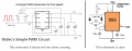
Hello All, I'm currently an EET student planning out a senior capstone project. I need to make a PWM circuit to control a fan, I've found a circuit that uses a 555 timer online that I want to use, I'll attach the circuit.

I couldn't find out why these components are used within this circuit. Could anyone help to explain why each component is used where it is?

Thanks
 

Attachments

dl324

Joined Mar 30, 2015
16,841
Welcome to AAC!

Are you supposed to design the PWM circuit yourself or be able to analyze designs that you use?

Personally, I'd stay away from anyone who draws schematics like that.
 

crutschow

Joined Mar 14, 2008
34,281
Here's an explanation of the 555 ---
The 555 operation is fairly simple.
It is a level-triggered latch (flip-flop) with a an added DIScharge output to reset the timing capacitor.
When the TRIG voltage goes below 1/3 Vcc, the latch is set (OUT high and DIS open).
If the TRIG voltage is back above 1/3 Vcc, then when the THRS voltage goes above 2/3 Vcc, the latch is reset (OUT low, and DIS connected to ground to discharge the timing capacitor).
It stays low until a low on the TRIG input again sets the latch (if the THRS voltage is below 2/3 Vcc).
From that you should be able to understand the operation of the 555 in it's various modes of operation, such as astable and monostable multivibrator.
 
Last edited:

LowQCab

Joined Nov 6, 2012
4,023
It would seem to me that the entire purpose of your project is to demonstrate to
your Instructor that You understand how the various components work together,
but You are asking us to teach You, via a Forum no less, what You were supposed to be learning in class,
and that's not fair to anyone.

Maybe you'd like to skip learning a new, (to You), Chip like the 555 ?
Are You familiar with the standard, basic, (theoretical), "Ideal-Op-Amp" model ?
If so, see if You can wrap your head around the following Schematic ..........

You also didn't specify any Voltages,
or whether You need to include the Power-Section and the expected Load characteristics.
.
.
.
PWM Comparitor .PNG.
 

crutschow

Joined Mar 14, 2008
34,281
You are asking us to teach You, via a Forum no less, what You were supposed to be learning in class,
and that's not fair to anyone.
I think you are being unduly critical.

I doubt that the classroom is instructing students how a 555 timer works so I think it's legitimate (and good) for him to ask a question about its operation, not just blindly use a cookbook circuit without understanding.
He's not asking us to design the circuit, or do homework, as many students do.

And I think my answer is a simple explanation of the 555 design that allows him to understand the 555 operation.

I see nothing unfair about all that.
 

DickCappels

Joined Aug 21, 2008
10,153
With @crutschow 's excellent description in post #3 in one hand and a copy of the NE555 datasheet from Texas Instruments (attached) in the other you should find it not too difficult to figure out why each component is there.

I think you will find section 8.3.2, A-stable Operation, to be of particular help along with the formula for finding Duty Cycle being the third formula from the bottom of the page.


Questions? Ask away.
 

Attachments

Top