 Facebook
 Google
 GitHub
 Linkedin
Hi all. This is my first post.
I have a number of DC motors and their speed controllers - which all require pulses to change their motor speeds.
I wish to use them for another purpose, where I want to start them and control their speeds with a rotary encoder switch.
These motor controllers require pulses to make them run the motors faster on one terminal and to slow them down on another terminal.
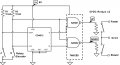
I determined that I can do this with a rotary encoder, but need to separate the pulses resulting from CW and CCW turning of the encoder.
This is my plan, but a first breadboard attempt didn't work.
I just connected a couple of LEDs to the output of my 'decoder' to try it out, so I could see the pulses on either output.
Am I missing something or have I just made a logic mistake somewhere?

I have a number of DC motors and their speed controllers - which all require pulses to change their motor speeds.
I wish to use them for another purpose, where I want to start them and control their speeds with a rotary encoder switch.
These motor controllers require pulses to make them run the motors faster on one terminal and to slow them down on another terminal.
I determined that I can do this with a rotary encoder, but need to separate the pulses resulting from CW and CCW turning of the encoder.
This is my plan, but a first breadboard attempt didn't work.
I just connected a couple of LEDs to the output of my 'decoder' to try it out, so I could see the pulses on either output.
Am I missing something or have I just made a logic mistake somewhere?
Attachments
-
 45.2 KB Views: 7
Last edited:
")


