PSIM Buck-Boost not working

Thread Starter

declan2693

Joined Feb 2, 2018
37
Hi guy,

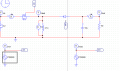
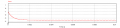
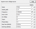
I cant seem to get the buck boost circuit to work. I have an input of 4.2 and want an output of 5V. I have the duty cycle calculated at 0.54. The frequency at 1.7Mhz. I am obviously setting it up as a boost.
Does anyone know what the problem is with my circuit?

Please ignore the second control as once I get it work with a diode I will be replacing it with a mosfet.
 

Attachments

Alec_t

Joined Sep 17, 2013
14,280
Most MOSFETS need a much higher clock voltage to work properly. Check the datasheet for the particular FET you want to use.
 

Thread Starter

declan2693

Joined Feb 2, 2018
37
Most MOSFETS need a much higher clock voltage to work properly. Check the datasheet for the particular FET you want to use.
I changed the input voltage up too 4V to no change at all. I dont see why I would need a higher voltage at switch, the diode is 0.7V to turn on.
 

Thread Starter

declan2693

Joined Feb 2, 2018
37
Many members here use LTspice for simulations. Maybe a psim file would run in LTS with a tweak or two. Add a ".txt" extension to the file name and post it.
I just tried what you said but when I try to upload the file the psim extension expands the txt too txt.psim..
 

crutschow

Joined Mar 14, 2008
34,280
I changed the input voltage up too 4V to no change at all. I dont see why I would need a higher voltage at switch, the diode is 0.7V to turn on.
What diode?
The switch is a MOSFET which typically requires at least a Vgs of 10V to fully turn on.
I have the correct set up for a buck-boost dc/dc converter.
But the output is a negative voltage which you stated you didn't want.
 

Thread Starter

declan2693

Joined Feb 2, 2018
37
What diode?
The switch is a MOSFET which typically requires at least a Vgs of 10V to fully turn on.
But the output is a negative voltage which you stated you didn't want.
Ok I see what your saying. Due to high resistance side. Ok so ive taken your advice and put 12V input voltage mosfet and still exact same results on voltage across output and inductor.

The output is negative which would be right for a non inverting buck-boost. My mistake, sorry about that.
 

crutschow

Joined Mar 14, 2008
34,280
Here's my LTspice simulation of your circuit:
The diode is a Schottky type for low forward drop and no recovery time (fast switching).
Note that, since it's an N-MOSFET switch, the common for the clock driver is connected to the MOSFET source terminal.
I could use a 5V clock, since that particular MOSFET is a logic-level type.

upload_2018-2-3_10-43-57.png
 

Attachments

Last edited:

Thread Starter

declan2693

Joined Feb 2, 2018
37
Here's my LTspice simulation of your circuit:
The diode is a Schottky type for low forward drop and no recovery time (fast switching).
Note that, since it's an N-MOSFET switch, the common for the clock driver is connected to the MOSFET source terminal.
I could use a 5V clock, since that particular MOSFET is a logic-level type.

View attachment 145097

Ok so you got it too work with the same values, then what could be wrong with mine?
 
Top