 Facebook
 Google
 GitHub
 Linkedin
Hi People, mature PIC & C Noob here,
I've worked through the LED Test progs (fine), Connected the EUSART/terminal (fine), switched the LEDs via terminal (fine), but my project will also require that I use EEPROM to store config data, so I thought I try a basic test....
Attempting to write some data to EEPROM and read it back, I'm getting some unexpected results. As my experience with C is limited (but I'm learning fast) I ask you guys to cast an eye over it. Any assistance would be appreciated.
Regards
Les
Technical stuff :
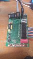
Hardware
PIC16F18877 PDIP40
ICD3
ICD Demo Board
Ext PSU
Software
MPLABX vers4.10
XC8 Vers2.0
Tera Term Vers4.99
I've worked through the LED Test progs (fine), Connected the EUSART/terminal (fine), switched the LEDs via terminal (fine), but my project will also require that I use EEPROM to store config data, so I thought I try a basic test....
Attempting to write some data to EEPROM and read it back, I'm getting some unexpected results. As my experience with C is limited (but I'm learning fast) I ask you guys to cast an eye over it. Any assistance would be appreciated.
Regards
Les
Code:
#include "mcc_generated_files/mcc.h"

/*
  Main application
 */
void main(void)
{
  // initialize the device
  SYSTEM_Initialize();

  uint8_t a;
  uint16_t i;

  TRISC = 0x00;
  __delay_ms(1000); // wait for everything to stabilise

  a=0x00;
  //WRITE TO EEPROM
  for(i=0;i<8;i++)
  {
  DATAEE_WriteByte(i, a);
  __delay_ms(40);   // Double the suggested 20ms
  a = a<<1;
  }
  //READ BACK TO LEDS
  do
  {
  for(i=0;i<8;i++)
  {
  PORTC = DATAEE_ReadByte(i);
  __delay_ms(300);
  }
  }while(1);
}

/**
 End of File
*/
Technical stuff :
Hardware
PIC16F18877 PDIP40
ICD3
ICD Demo Board
Ext PSU
Software
MPLABX vers4.10
XC8 Vers2.0
Tera Term Vers4.99
Attachments
-
 176 KB Views: 5
 -
2.3 KB Views: 6
-
11.8 KB Views: 10
-
11.8 KB Views: 6


