Facebook
 Google
 GitHub
 Linkedin
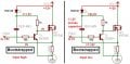
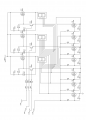
I was trying to combine two side switch using MOSFET. both using IRF530 as the high and low side switch. It work perfectly when I used 1 seven-segment, but it began to throw error after i tried to have 2 additional seven-segments.
[SPICE] DELMIN increased to 1.11022e-016 due to lack of time percision
[SPICE] transient GMIN stepping at time =0.501998
[SPICE] TRAN: Time step too small; timestep = 1.38778e-017: trouble with node ...
I have the circuit pic attached.
I don't have a good electrical engineering background. but I guess the circuit is wrong?
Please, help.
Attachments
-
 6.9 KB Views: 199