Problem with stepper motor functioning

Thread Starter

thavamaran

Joined Feb 21, 2008
67
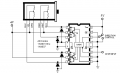
Hi everyone, im currently working on stepper motor, im using UCN5804 as my
stepper motor driver, then i connect PIC 16f877A as my indexer to run the motor. i have wrote a C program for PIC which im not sure correct or no, im really new
with C. Here is the coding i wrote for PIC, and i attach the stepper motor datasheet, UCN5804B datasheet, and the schematic as well. please help me out.
Stepper motor im using is PX243-01AA.

Here the RB0 is connected to Direction Pin of UCN5804B and RB1 is connected to Step input pin of UCN5804B.

#include <htc.h>
#include "delay.h"
__CONFIG(0x3f71);

void main (void)
{
unsigned char i;
TRISB = 0x00;

RB0 = 1;

for (i=0; i<60; ++i)
{
RB1 = 1;
DelayUs(1000);
RB1 = 0;
DelayUs(1000);
}
}
 

Attachments

SgtWookie

Joined Jul 17, 2007
22,230
When you're posting source code, you should use the CODE blocks to preserve the formatting, like:
Rich (BB code):
#include <htc.h>
#include <delay.h>
 __CONFIG(0x3f71);

void main(void)
{
   unsigned char i;
   TRISB = 0x00;

   RB0 = 1;

   for (i=0; i<60; ++i)
   {
      RB1 = 1;
      DelayUs(1000);
      RB1 = 0;
      DelayUs(1000);
   }
}
On the "Go Advanced" button page, there is a "#" sign in the menu which inserts the code blocks.

You had a space between "main" and (void).

You didn't turn off the watchdog timer, and you aren't taking care of resetting it in your code. Without that, the uC will re-boot every few milliseconds, and it will seem like your code is never getting executed.

Here's one sample config line that turns off the watchdog timer:
__CONFIG(INTIO & WDTDIS & MCLRDIS & BORDIS & UNPROTECT & PWRTEN);

Try looking at some of the sample code that came with your compiler.

Also, post a schematic of how you have your uC connected up.
 

Thread Starter

thavamaran

Joined Feb 21, 2008
67
Hi wookie, sorry for the very late reply, was very busy with some other assignments, anyway i already came out with the schematic and a bit changes in the coding.

Rich (BB code):
#include <htc.h>
#include "delay.h"
__CONFIG(0x3f71);

void main (void)
{
	unsigned char i;
	TRISB = 0x00;

	RB1 = 1;

	while ( 1 )
	{
		for (i=0; i<60; ++i)
		{
			RB2 = 1;
			DelayMs(1);
			RB2 = 0;
			DelayMs(1);
		}
	}
}
anyway as what i have found out, 0x3f71 automatically off the watchdog timer. im not pretty sure about it.

and i also have attached the schematic. thank you.
 

Attachments

SgtWookie

Joined Jul 17, 2007
22,230
The .BMP file in the ZIP attachment was nearly 2MB! I converted it to a .PNG file using MSPaint, and now it's just 33kb; it's attached.

You don't show the diodes connected to the stepper motor wires in your schematic - where are they?

You don't have +4v going to the stepper. Not going to work without it.

Do you get a signal on RB2 alternating between 5v and 0v?
 

Attachments

thatoneguy

Joined Feb 19, 2009
6,359
For a 16F877, sample code for one revolution:

Rich (BB code):
1: #include[SIZE=+1]<pic[SIZE=+1].[/SIZE]h[SIZE=+1]>[/SIZE]                   //include MCU head file
 2: __CONFIG[SIZE=+1]([/SIZE]0x1832[SIZE=+1])[/SIZE][SIZE=+1];[/SIZE]        
 3: 
 4: char step1[SIZE=+1]=[/SIZE]9[SIZE=+1];[/SIZE]                     //the first step
 5: char step2[SIZE=+1]=[/SIZE]0x0c[SIZE=+1];[/SIZE]                  //the second step
 6: char step3[SIZE=+1]=[/SIZE]6[SIZE=+1];[/SIZE]                     //the third step 
 7: char step4[SIZE=+1]=[/SIZE]3[SIZE=+1];[/SIZE]                     //the fourth step
 8: 
 9: void delay[SIZE=+1]([/SIZE][SIZE=+1])[/SIZE][SIZE=+1];[/SIZE]                     //delay function declare
10: 
11: //**********************main function*************************
12: void main[SIZE=+1]([/SIZE][SIZE=+1])[/SIZE]
13: [SIZE=+1]{[/SIZE]
14:   char  loop[SIZE=+1];[/SIZE]                     //circle variable declare
15:   ADCON1[SIZE=+1]=[/SIZE]0x7[SIZE=+1];[/SIZE]                     //set A PORT all general data PORT
16:   TRISA[SIZE=+1]=[/SIZE]0X00[SIZE=+1];[/SIZE]                     //set A PORT OUTPUT
17:   for[SIZE=+1]([/SIZE]loop[SIZE=+1]=[/SIZE]12[SIZE=+1];[/SIZE]loop[SIZE=+1][SIZE=+1]-[/SIZE][SIZE=+1]-[/SIZE][/SIZE][SIZE=+1];[/SIZE][SIZE=+1])[/SIZE]            //circle times of stepper motor rotate one time 360/(7.5*4)
18:      [SIZE=+1]{[/SIZE]
19:          PORTA[SIZE=+1]=[/SIZE]step1[SIZE=+1];[/SIZE]             //drive the first step 
20:          delay[SIZE=+1]([/SIZE][SIZE=+1])[/SIZE][SIZE=+1];[/SIZE]                 //delay
21:          PORTA[SIZE=+1]=[/SIZE]step2[SIZE=+1];[/SIZE]             //drive the second step 
22:          delay[SIZE=+1]([/SIZE][SIZE=+1])[/SIZE][SIZE=+1];[/SIZE]    
23:          PORTA[SIZE=+1]=[/SIZE]step3[SIZE=+1];[/SIZE]             //drive  the third step 
24:          delay[SIZE=+1]([/SIZE][SIZE=+1])[/SIZE][SIZE=+1];[/SIZE]
25:          PORTA[SIZE=+1]=[/SIZE]step4[SIZE=+1];[/SIZE]             //drive  the fourth step 
26:          delay[SIZE=+1]([/SIZE][SIZE=+1])[/SIZE][SIZE=+1];[/SIZE]
27:      [SIZE=+1]}[/SIZE]
28:   while[SIZE=+1]([/SIZE]1[SIZE=+1])[/SIZE]                        //stop work
29:      [SIZE=+1]{[/SIZE]
30:          PORTA[SIZE=+1]=[/SIZE]0[SIZE=+1];[/SIZE]
31:      [SIZE=+1]}[/SIZE]
32:  [SIZE=+1]}[/SIZE]
33: 
34: //**********************delay function***********************
35: void  delay[SIZE=+1]([/SIZE][SIZE=+1])[/SIZE]
36:  [SIZE=+1]{[/SIZE]
37:     char i[SIZE=+1],[/SIZE]j[SIZE=+1];[/SIZE]
38:     for[SIZE=+1]([/SIZE]i[SIZE=+1]=[/SIZE]100[SIZE=+1];[/SIZE]i[SIZE=+1][SIZE=+1]-[/SIZE][SIZE=+1]-[/SIZE][/SIZE][SIZE=+1];[/SIZE][SIZE=+1])[/SIZE]
39:        [SIZE=+1]{[/SIZE]
40:           for[SIZE=+1]([/SIZE]j[SIZE=+1]=[/SIZE]255[SIZE=+1];[/SIZE]j[SIZE=+1][SIZE=+1]-[/SIZE][SIZE=+1]-[/SIZE][/SIZE][SIZE=+1];[/SIZE][SIZE=+1])[/SIZE][SIZE=+1];[/SIZE]
41:        [SIZE=+1]}[/SIZE]
42:  [SIZE=+1]}[/SIZE]

[/SIZE]


Code made pretty by: http://www.chamisplace.com/colorizer/cc.asp
 

SgtWookie

Joined Jul 17, 2007
22,230
Thatoneguy,
He's just trying to send a clock to RB2 to cause his stepper to move.
Your code is really for use as a generic driver for a ULN2803A IC or the like.
It wouldn't do much for our OP, I'm afraid.
 

thatoneguy

Joined Feb 19, 2009
6,359
My bad!

It outputs 1001, 1100, 0110, 0011, and repeats, for driver transistors on RA0-RA3.

I'll leave it for reference for the next person searching, i guess.

All apologies for missing the driver details!
 

Thread Starter

thavamaran

Joined Feb 21, 2008
67
Hi Wookie, im extremely sorry about the size, i was rushing yest with the schematic so that i can at least show you what i did, sorry about that, on the UCN5804B site i built it according to the schematic you did for me. here it is. i haven't check the output pulse with any oscilloscope, but i suspect my crystal got toasted. im fixing a new crystal later on and i will redo again and let you know by tonight, tonight is according to malaysia:cool:.

thatoneguy, thanks for the coding man, but too bad im only using two output pin from PIC and my driver spec is different from your coding, anyway thanks a lot.
 

Attachments

Thread Starter

thavamaran

Joined Feb 21, 2008
67
Hey wookie, its working, my stepper is working with the pic, at last got it spinning, thanks a lot man, thanks a lot for your time and thatoneguy, thanks to too.
 

SgtWookie

Joined Jul 17, 2007
22,230
Good news! :D
Yeah, crystals are pretty fragile - they break mighty easy. Dropping them on a hard surface or over-driving them will kill them in a hurry.
 

Thread Starter

thavamaran

Joined Feb 21, 2008
67
Thanks again wookie, just wanted to ask you a question, can i know how you are damn good in all this stuff man? im mesmerized! adioZ!
 
Top