Problem With Op-Amp Comparator

Thread Starter

HeWasOnly3

Joined Sep 2, 2010
12
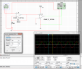
Hi gurus, currently I'm trying to do a simulation on a question regarding comparator. First of all the question requires me to use an input of 200mVpp, 500 Hz(Which can be achieved by using a Function Generator) and output it to a square wave 0 to 5V. So for my attempt to do this question, I have used a non- inverting amplifier and a comparator to solve this question. Okay, the thing that I don't understand is that why my output is 743mV to 4.27V instead of 0V to 5V? Here is my circuit constructed using Multisim. Many thanks :D
 

Attachments

bertus

Joined Apr 5, 2008
22,995
Hello,

There are two main problems with the circuit.

1) the input signal give both + and - signals, but the opamp is single powered.

2) the second opamp compares to ground, but the signal probably wont go negative.

Take a look at the attached PDF for single supply opamp circuits.

Bertus
 

Attachments

Thread Starter

HeWasOnly3

Joined Sep 2, 2010
12
Hello,

There are two main problems with the circuit.

1) the input signal give both + and - signals, but the opamp is single powered.

2) the second opamp compares to ground, but the signal probably wont go negative.

Take a look at the attached PDF for single supply opamp circuits.

Bertus
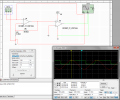
Okay I have corrected the first mistake but it looks weird. You see if I connect both + and - of the input, I will have to set the Amplitude to 50mVp in order to achieve 200mVpp. In contrast to my previous circuit in which I use only + and ground input, I need to set Amplitude to 100mVp in order to achieve 200mVpp. I have read the pdf file that you have uploaded however I still cant get 0 to 5V square wave result. Here is my modified circuit.
 

Attachments

thatoneguy

Joined Feb 19, 2009
6,359
What you are trying to build is a zero crossing detector with dual polarity output.

Google should give you good ideas. sound.westhost.com has a few schematics for this.
 

Thread Starter

HeWasOnly3

Joined Sep 2, 2010
12
What you are trying to build is a zero crossing detector with dual polarity output.

Google should give you good ideas. sound.westhost.com has a few schematics for this.
I have read that and tried the circuit, however it still wont produce 0 to 5V output hmmm....:(
 
The output limitations are a function of the opamp. Their output does not typically reach the supply rails that power it. To get closer, there are "rail-to-rail" output opamps that achieve voltage outputs that are much closer to the supply rails. However, they also do not typically achieve the exact 0V and 5V that you are looking for.

Here is an example data sheet for a "rail-to-rail" opamp. Page 5 has output characteristics. It shows that with low currents the high and low output, V(oh) and V(ol) get within millivolts of the supply rails, V(cc) and V(ee). However, with larger output currents the output voltages get further and further away from the rails.

Opamps without the "rail-to-rail" capabilities start with their output further away even at low output currents...

DATASHEET: http://www.analog.com/static/imported-files/data_sheets/AD822.pdf
 
Last edited:

Kermit2

Joined Feb 5, 2010
4,159
Adding a mosfet switch to the output might get you closer to your 0 volt / 5 volt levels.

A logic level mosfet preferably, so the 4.something volt signal can push it into full conduction.
 
Top