Problem using PWM with high power LEDs

Thread Starter

eggwardo

Joined Feb 2, 2024
3
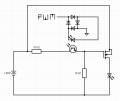
Trying to design a photo-enlarger, and as part of it, I need to be able to control the relative brightness of a 20w cobb led thats powered off of 30v. I'm trying to use an off the shelf mosfet board (HW-700) that I had around that I can use alongside an arduino to control the led using pwm. However, no matter what I do, it doesnt seem to be working. Based on my (granted, rudimentary probing), the board config roughly looks like this:

1706910569073.png
I've added the 30v connection and the led coming off the mosfet shown above.

It's relatively basic, full-bridge rectifier sending the pwm signal to the octocoupler input, supposedly switching the phototransistor on and off, turning on and off the mosfet that controls the LED. I've verified that the PWM signal looks good from the arduino on the oscilloscope, but for some reason the voltage coming from the emitter of the octocoupler is only around .5v instead of the expected 15v. I've swapped out optocouplers, but there seems to be no difference. I'm using a V0615a optocoupler, HA210N06 mosfet btw.

Any advice would be appreciated.
 

Attachments

Thread Starter

eggwardo

Joined Feb 2, 2024
3
Trace the signal levels from your 'bridge' rectifier.

View attachment 314238

Where is your equivalent points C and D on your rectifier circuit?
Oops, I see what you mean from my diagram above. I did draw it the rectifier incorrectly. In reality, the board uses an ic, so I don't think that the problem lies there. Nevertheless, I just measured it and the signal seems fine.
 

Alec_t

Joined Sep 17, 2013
14,430
I would have expected the LED to be in the drain path, not in the source path? Are you sure your schematic represents the 'MOSFET board' correctly?
 

Thread Starter

eggwardo

Joined Feb 2, 2024
3
I would have expected the LED to be in the drain path, not in the source path? Are you sure your schematic represents the 'MOSFET board' correctly?
yes, you're correct. I definitely should've been more careful in recreating the circuit faithfully. Lesson learned.
 

geekoftheweek

Joined Oct 6, 2013
1,268
What optocoupler are you using? Why the rectifier if you are running it from an Arduino or is that just for testing? Also the 10k going in to the optocoupler is way too much for a 5V input. It's probably barely lighting the LED if at all.

Edit:

I missed the off the shelf part in the original post... that answers a few questions.
 
Last edited:

MisterBill2

Joined Jan 23, 2018
19,630
With the LED below the source connection you will not be developing enough gate to source voltage to turn it in very much. Power mosfets need a good voltage, gate to source, to switch on. Probably the 10K resistor does not help much either.
 

LowQCab

Joined Nov 6, 2012
4,356
Since You are obviously new to Electronics,
You may not actually know what questions You should be asking,
and what information that You need to be providing.

Providing a Schematic is a very good thing, 2-thumbs-up,
however, everything is wrong with it, it won't work, and may instantly blow-out the LED.
But this is only a partial Schematic,
it is important to include the source of the PWM-Signal so that
guaranteed compatibility can be built-in to the new Circuit.

Please provide all PDF Spec-Sheets for every Component that You currently have or intend to use.

Is it convenient for You to order parts from one of the big Electronics-Suppliers, like DigiKey ?

What is the overall purpose of this project ?

Why are You using an Arduino to generate the PWM-Signal ?

Do You already have the desired LED that You would like to use ?
Do You need help in choosing an LED for your Project ?

Why is your Power-Supply ~30-Volts ?, ~30-Volts is Waaay higher than is needed,
please describe your Power-Supply and provide all specifications.
This High of a Voltage will require a Switching-Current-Regulator for efficient, and cool operation.
Otherwise, large High-Power-Resistors will be required.

With as much information as possible,
You may be provided with a workable Schematic and Parts-List,
and an explanation of how and why it works,
and the reasons why certain particular Components where chosen.
.
.
.
 

geekoftheweek

Joined Oct 6, 2013
1,268
I did some looking around as this was kind of stuck in my head. It seems the module (HW-700) is something that is normally used with 3D printers and there are a number of youtube videos about it.

In a nutshell it is a NFET so the module will need to be in the (-) side of the LED circuit.
In the video I watched they found you need somewhere between 5 and 9 volts as your on signal to get it to work.

You will need some form of current limiter for your LED. It's actually good it hasn't worked for you yet...

This is the video I checked out
.

There is no guarantee your module is exactly the same, but it's fairly safe to say all modules are going to work the same.
 

MisterBill2

Joined Jan 23, 2018
19,630
I have assemblies with sort of high power and the LED strings use about 72 volts at the rated current. SO TH REQUIRED VOLTAGE DEPENDS on the led module to be powered. If there are 24 LEDs in the string with a forward drop of 3.1 volts at the rated current then 30 volt supplies will not be adequate.
 

panic mode

Joined Oct 10, 2011
2,919
as already mentioned there is a number of problems you are facing:
the components are not enumerated (R1,R2... D1,D2, D3...) one cannot even have a proper conversation without that.
the bridge rectifier you have drawn is incorrect and will not work. here i reversed D3 and D4 for you. if this is something you made using diodes, check it again. as it is shown there will be no current through the optocoupler LED and of course the optocoupler output will not be 15V you expect it will be much closer to zero. btw the optocoupler you have is not the exact part number. it is missing the suffix. without it one can only assume worst case CTR or about 50%. the R1 value need to be selected based on PWM voltage. if the bridge rectifier issue is corrected you will still have about 3V drop across bridge and opto. so if input voltage is 9V, you will only get 6V across R1. that means current of only 0.6mA. and because of 50% CTR, optocoupler output will not be saturated. in other words you will get up to 50% of the the 0.6mA which is not enough. If you connect R2 and R3 without optocoupler to 30V, their current will be 30V/(2*10k)=1.5mA. your optocoupler must be able to handle that. but because of crappy CTR ratio, you need at least 3 mA through R1 (preferably 5mA). so for PWM signal that is 9V, R1 will need to be lower no more than 6V/5mA = 1.2k. the biggest issue is the MOSFET connections. this thing is wired backwards. also the load (cob LEDs) need to be on the positive side. and without specs on the LEDs we cannot tell if this will work or not.

1707098885164.png
 
Last edited:
Top