problem in matlab simulink

Thread Starter

spidermanIIII

Joined Nov 22, 2013
78
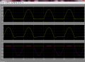
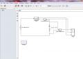
i need help, i asked to do simulation of half wave uncontrolled rectifier with R-L load with matlab for R=100 ohm and L=10 mH , i built the schematic and run but output is different about we study.
here the file i created with matlab 2013
 

Attachments

shteii01

Joined Feb 19, 2010
4,644
A) None of your work is labeled.
Three plots in RL_out don't tell me jack.

B) What frequency are you using?
I did a sim using MultiSim and at 60 Hz there is not much to see. Then I tried 200 Hz and I saw VL like they show it in your book illustration VL=VO-VR.
vl.jpg


Vout is red. Vresistor is green. Vinductor=Vout-Vresistor=975.4-678.1= about 300 mV.
 

Thread Starter

spidermanIIII

Joined Nov 22, 2013
78
A) None of your work is labeled.
Three plots in RL_out don't tell me jack.

B) What frequency are you using?
I did a sim using MultiSim and at 60 Hz there is not much to see. Then I tried 200 Hz and I saw VL like they show it in your book illustration VL=VO-VR.
View attachment 74005


Vout is red. Vresistor is green. Vinductor=Vout-Vresistor=975.4-678.1= about 300 mV.
i am sorry the source is ac its value 220 RMS and frequency is 50 Hz
the first graph is V out
the second is I
the third is diode voltage and current
 
Top