 Facebook
 Google
 GitHub
 Linkedin
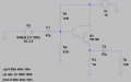
I have an emitter-follower circuit utilizing a TIP120. I have tried half a dozen
different TIP120s with the same result.
The dc voltages are:
Collector 15.00V
Base 1.96V
Emitter 1.22V
Vbe = 0.7V but shouldn't it be 1.4V with a darlington device?
I have also tried different biasing voltages with no luck.
New proto board. No loose connections or wiring issues.
David
different TIP120s with the same result.
The dc voltages are:
Collector 15.00V
Base 1.96V
Emitter 1.22V
Vbe = 0.7V but shouldn't it be 1.4V with a darlington device?
I have also tried different biasing voltages with no luck.
New proto board. No loose connections or wiring issues.
David
Attachments
-
1.9 KB Views: 23
-
 367.6 KB Views: 31


