Facebook
 Google
 GitHub
 Linkedin
This is a follow-up to this thread, which I thought was solved, but it's not: https://forum.allaboutcircuits.com/...o-a-ucontroller-with-an-opto-isolator.159447/
I've made a tachometer that takes input from the stator wire on a 12V alternator on my boat, into a 4N37 optocoupler, then into a Wemos D1 Mini (an ESP8266 microcontroller). If I can get a nice, clean pulse from the opto and into the Wemos, the software that converts those pulses into Hertz (and eventually RPM) works fine. I have tested it by using an Arduino Uno to pulse one of the digital pins on/off every few milliseconds, and using the output of that digital pin as the input into the optocoupler. When I do that, it works perfectly - 495 Hz out of the Arduino gives me 495 Hz out of the Wemos. (Same for 250 Hz, and 330 Hz, and any other frequency I've tested.)
But when I use the alternator's output as the input to my optocoupler, I get output that is too high, and erratic. At the engine's idle speed, the pulse coming from the alternator is about 260 Hz (258 to 260). That's what the math says it should be (alternator RPM, measured with a handheld digital tach, is 1,950. 1950 / 60 is 32.5 revolutions per second. 32.5 x 8, which is the number of pulses that the Balmar alternator outputs each revolution, is 260). That's also what my cheapo DSO138 oscilloscope says it is. But the output from the Wemos (counted using an interrupt on the input pin) shows from 285 to 310, with all kinds of numbers in between, changing all the time.
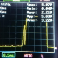
So it seems that I'm getting some noise, or something, in the circuit, that's present only when using the higher voltage from the alternator. My oscilloscope shows the voltage to be 16V to 18V, with what looks to me to be a nice, consistent signal shape. Picture below.
 (I didn't have the scope properly zero'd, which is why it shows -5.23V up to 11.68. It's actually 0V to 16.91.)
Below is the schematic of my circuit. I used a battery symbol for the alternator because Fritzing doesn't have a symbol for an alternator.

(I didn't actually use a 7805 voltage regulator, but I can't find an object in Fritzing for the adjustable buck converter that I've actually used. I know a 7805 needs capacitors, but the buck converter seems to have those built in.)
What have I done wrong? What have I left out? What could cause an erratic, and "inflated", count on an interrupt pin on a microcontroller?
I've made a tachometer that takes input from the stator wire on a 12V alternator on my boat, into a 4N37 optocoupler, then into a Wemos D1 Mini (an ESP8266 microcontroller). If I can get a nice, clean pulse from the opto and into the Wemos, the software that converts those pulses into Hertz (and eventually RPM) works fine. I have tested it by using an Arduino Uno to pulse one of the digital pins on/off every few milliseconds, and using the output of that digital pin as the input into the optocoupler. When I do that, it works perfectly - 495 Hz out of the Arduino gives me 495 Hz out of the Wemos. (Same for 250 Hz, and 330 Hz, and any other frequency I've tested.)
But when I use the alternator's output as the input to my optocoupler, I get output that is too high, and erratic. At the engine's idle speed, the pulse coming from the alternator is about 260 Hz (258 to 260). That's what the math says it should be (alternator RPM, measured with a handheld digital tach, is 1,950. 1950 / 60 is 32.5 revolutions per second. 32.5 x 8, which is the number of pulses that the Balmar alternator outputs each revolution, is 260). That's also what my cheapo DSO138 oscilloscope says it is. But the output from the Wemos (counted using an interrupt on the input pin) shows from 285 to 310, with all kinds of numbers in between, changing all the time.
So it seems that I'm getting some noise, or something, in the circuit, that's present only when using the higher voltage from the alternator. My oscilloscope shows the voltage to be 16V to 18V, with what looks to me to be a nice, consistent signal shape. Picture below.
(I didn't have the scope properly zero'd, which is why it shows -5.23V up to 11.68. It's actually 0V to 16.91.)Below is the schematic of my circuit. I used a battery symbol for the alternator because Fritzing doesn't have a symbol for an alternator.
(I didn't actually use a 7805 voltage regulator, but I can't find an object in Fritzing for the adjustable buck converter that I've actually used. I know a 7805 needs capacitors, but the buck converter seems to have those built in.)
What have I done wrong? What have I left out? What could cause an erratic, and "inflated", count on an interrupt pin on a microcontroller?