problem controlling variable DC-DC LTC1261LCS8-4

Thread Starter

yef smith

Joined Aug 2, 2020
856
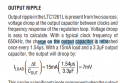
Hello,In the datasheet shown below they say that the output resistance could be controlled using the COMP pin.
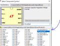
I have tried to simulate this component in LTSPICE.
However I cannot understand the datasheet regarding how exactly do I need to use the COMP pin for tuning the output voltage?
LTSPICE file is attached.
Thanks.

https://www.analog.com/media/en/technical-documentation/data-sheets/1261lfa.pdf

1713081537791.png
1713082293925.png1713081205989.png
 

Attachments

Last edited by a moderator:

Irving

Joined Jan 30, 2016
4,088
The device in the simulation is the fixed -4v version. A resistor to ground will raise the output voltage (towards 0v) , and to Vout will lower it. But it's only to trim the voltage a few %. To set a specific voltage you need the adjustable version (no -4 suffix)
 

Irving

Joined Jan 30, 2016
4,088
Page 10 & figure 5 of the data sheet tells you all you need to know. It's always worth reading datasheets completely, they aren't always logically arranged!
 

Thread Starter

yef smith

Joined Aug 2, 2020
856
Hello Irving,I did exactly like the datasheet and its working exactly by the formula,but I get these 0.3V jumps as shown below.
could you recommend me to make the output without those dips?
I tried to increase the capacitor on the output but its not improving the situation.
What could be done to eliminate those dips?
Thanks.
1713092090366.png

1713092538488.png1713090710544.png
 

Attachments

Last edited:

Thread Starter

yef smith

Joined Aug 2, 2020
856
Hello Irving,I have built an DC-DC which is supposed to be turned on and off using SHDN shown in the photos in the link.
Data sheet link of the DC-DC is also attached.
I want to turn it ON using 0V into SHDH and turn it OFF and discharge the output using 3.3V into SHDN(GPIO ).
The output needs to be discharged when the SHDN input 3.3V but my output of the component is set to -4V.
PMOS what chosen to discharge the output ,however PMOS cannot open and close like I want from a 0-3.3V directly to the gate of the PMOS as shown in the attached photos in the link.
There is a need to do level shifting to allow the PMOS to open when i what it.

I have chose a PMOS with Vt=-0.45 from datasheet shown below
I want the PMOS conducting using the formulas below:
Vs=0V Vd=-4V
conducting condition:
Vsg>0.45 --> 0-Vg>+0.45 Vg<-0.45

I need level shifter to make the PMOS conducting.
I learned previosly the level shifting could be done using zener diode using its reverse voltage value.
How do I implement voltage level shifting in my situation?
I know that we can do level shifting with Zener diode, if there is a good alternative i'll be happy to hear.

Thanks.
1713120625186.png1713120597007.png
 

Thread Starter

yef smith

Joined Aug 2, 2020
856
Hello Irving,when I look at the current going threw the mosfet i see 1A at peak which is much higher then what is possible at the datasheet shown below.
Maybe you could reccomend a BJT which i could use for this puprose?
Thanks.

1713126722369.png1713125392992.png1713125369063.png

1713126550359.png
 

Thread Starter

yef smith

Joined Aug 2, 2020
856
Hello Irving ,I need to learn how to do level shifting in case I’ll have to use the opposite pulse for the same discharge functionality .
Could you recommend me a good level shifting technique for the pulse which In my situation , I could take the input and change it so into the gate I’ll see shifted signal ,for example the input from 0-3.3 into -1.5 +1.5 for example or into -3 to -0.3 ?
Is there a good method you could recommend ?
Thanks .
 
Top