Probing my summing circuit

Thread Starter

tomshong

Joined Oct 6, 2011
36
Hi experts,

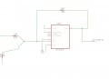
I built a standard summing circuit using LM318 following the schematic as shown. The only ‘load’ at Vout is the probe.

My problem is, when I first power it on, the scope came up nothing, but when I disconnect and reconnect the probe, suddenly I start seeing the expect waveform and the circuit works.

What could cause the problem?
 

Attachments

Last edited:

#12

Joined Nov 30, 2010
18,224
Yeah, right a generic drawing of a summing junction. That tells us all about it.
when I disconnect and reconnect the probe, suddenly I start seeing the expect waveform and the circuit works.
What could cause the problem?
The probe is stopping the circuit from starting up.
 

#12

Joined Nov 30, 2010
18,224
How would a probe from keeping the circuit from starting up? It's just a high impedance load, isn't it?
How would I know? Am I supposed to guess what kind of probe? What the power supply is? What frequency you are using? How you built the circuit?

"I was checking a lever and it won't move. Why won't it move?"
"How can checking it stop it from moving?"
 

Thread Starter

tomshong

Joined Oct 6, 2011
36
when i connect it up to the subsequent stage, the probe wasn't connected to anything, and nothing worked.

The only way I can make it work is if i open up the connection between the output of the summing circuit and the following stage, then reconnect it, then it works.

Attached is my summing circuit. It doesn't look much different than the generic schematic
 

Attachments

Last edited:

Thread Starter

tomshong

Joined Oct 6, 2011
36
How would I know? Am I supposed to guess what kind of probe? What the power supply is? What frequency you are using? How you built the circuit?

"I was checking a lever and it won't move. Why won't it move?"
"How can checking it stop it from moving?"
The power supply is +/- 9 volt, the two signals going in is 1) a sawtooth of about 25Mhz with about +/- 4Vpp and 2) a DC signal that varies between +/- 4volt using a pot. The summing circuit uses the DC to tune the offset of the sawtooth. I don't know the make and model of the probe. But at this point of my debugging I don't think it's the problem with the probe, since the same thing happens with the output connected to the subsequent stage without a probe, and the only way for it to work is if I manually sever the tie between the two stage then reconnect it before the summing circuit will work.

I then isolated this summing circuit and only connect the output to the probe, and i was able to reproduce the same problem.

It's as though the summing circuit wants to see an open circuit at the load first before seeing a load before it will turn on. I tried switching out the Opamp and it's still doing the same thing, so it's not an issue of faulty component.

What could cause this phenomenon?
 
Last edited:

#12

Joined Nov 30, 2010
18,224
The first thing I see is that the chip is good for 50 volts per microsecond with a +/- 15 volt supply and you are asking it for more than 628 volts per microsecond with a +/- 9 volt supply.
The large signal output range is rated at zero by the time you get to 15 MHz.
Definitely the wrong op-amp for this job.

As a matter of experience, I say you should place a resistor on the output of the chip to isolate it from any capacitance on the load side.
Still, you're lucky it works at all.
 

Attachments

Thread Starter

tomshong

Joined Oct 6, 2011
36
Thanks. Looks like the voltage I was driving it was indeed the culprit. When I crank up the external DC supply up to at least +/- 12 it started working again.

Looks like I will need to get a new onboard supply that gives it +/- 15 volts.

Thanks again for your help! :)
 
Top