Facebook
 Google
 GitHub
 Linkedin
Hi,
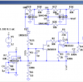
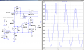
I'm working on a Wienbridge oscillator with JFET automatic gain control. The general idea of the oscillator is attached. It shows 2 sets of timing caps where I'll probably end up using 3 sets. With something like 2k - 50k and .47 nF, 10 nF, 250 nF the range would be from 12 Hz to 169 kHz, if I can make that work. It needs to be powered from a single supply, likely 12V.
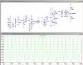
The JFET in the AGC loop gets bumped once every period correcting the gain. If you insert a rectifier in the loop the JFET gets bumped twice. From the FFT it looks like this significantly reduces the harmonics. It also looks like it marginally improves the flatness of the output amplitude over the frequency range. For these reasons I consider adding the extra complexity of a rectifier.
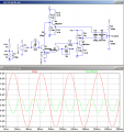
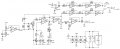
Now I'm trying to figure out a precision rectifier that is fast enough. See precision_rectifier.png for what I came up with. Powering a comparator from the reference voltage may not win me any prizes and I need to tweak R19 to give both lobes of the rectified sine approximately the same amplitude. Also there's a lot of junk on the tops. I tried to make the comparator drive a MOSFET that shorts the non-inverting input of U8 to Vref instead of directly connecting the open collector, but nothing good came of that. Can a MOSFET help here somehow?
What rectifier configuration would you suggest here?
I'm working on a Wienbridge oscillator with JFET automatic gain control. The general idea of the oscillator is attached. It shows 2 sets of timing caps where I'll probably end up using 3 sets. With something like 2k - 50k and .47 nF, 10 nF, 250 nF the range would be from 12 Hz to 169 kHz, if I can make that work. It needs to be powered from a single supply, likely 12V.
The JFET in the AGC loop gets bumped once every period correcting the gain. If you insert a rectifier in the loop the JFET gets bumped twice. From the FFT it looks like this significantly reduces the harmonics. It also looks like it marginally improves the flatness of the output amplitude over the frequency range. For these reasons I consider adding the extra complexity of a rectifier.
Now I'm trying to figure out a precision rectifier that is fast enough. See precision_rectifier.png for what I came up with. Powering a comparator from the reference voltage may not win me any prizes and I need to tweak R19 to give both lobes of the rectified sine approximately the same amplitude. Also there's a lot of junk on the tops. I tried to make the comparator drive a MOSFET that shorts the non-inverting input of U8 to Vref instead of directly connecting the open collector, but nothing good came of that. Can a MOSFET help here somehow?
What rectifier configuration would you suggest here?
Attachments
-
 61.3 KB Views: 48
 -
 26.6 KB Views: 43
 -
6.4 KB Views: 7