 Facebook
 Google
 GitHub
 Linkedin
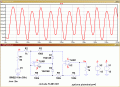
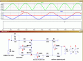
I built a precision full-wave rectifier using two opamps and two diodes in PSpice. The goal is to rectify and amplify an AC signal by 100x.
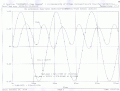
I did a time domain simulation and found that the output at 1kHz deviates little from the expected results, but at 30kHz there is considerable distortion.
Why did this happen? In this circuit setup, which opamp (U1 vs U2) is the more significant contributor to the distortion? Is there a way to extend the frequency range that gives little distortion?
I also performed a DC bias analysis by setting the input voltage source Vs to 0, but the output of OpAmps is non-zero. Why does this happen? Is it because the DC voltage supplies (Vcc and Vee) to the OpAmp energized the OpAmps and disturbed them a little? Is there way to make the non-zero output go away?
Thanks.
(I attached the circuit diagram and simulation results. In the simulation results, the input voltage was multiplied by 100 for viewing convenience).
MOD: rotated and clipped your circuit image, makes it easier to read with your text.E
Attachments
-
1 MB Views: 33
-
1.1 MB Views: 48
-
1.1 MB Views: 12
-
2.4 MB Views: 8
Last edited by a moderator:


") At my age remastering the use
At my age remastering the use


