Facebook
 Google
 GitHub
 Linkedin

Hello,
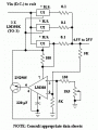
I have seen several circuits similar to the attached one. I can understand how the upper part works (Voltage regulator ICs...), but I find some difficulties in the lower part. Here are some questions:
1) Why the op-amp IC is fed through a 100 resistor and from the adjust's of the voltage regulator ICs?
2) What does the connection between pin 7 and the output of U3 do?
3) The feed back through the 5k resistor, the transistor connection... why are they connected like that??

I have seen several circuits similar to the attached one. I can understand how the upper part works (Voltage regulator ICs...), but I find some difficulties in the lower part. Here are some questions:
1) Why the op-amp IC is fed through a 100 resistor and from the adjust's of the voltage regulator ICs?
2) What does the connection between pin 7 and the output of U3 do?
3) The feed back through the 5k resistor, the transistor connection... why are they connected like that??
Attachments
-
 4 KB Views: 454
Last edited:


 Too slow, get back.