Power supply with LM317 Advices needed.

Thread Starter

jm-X

Joined Feb 12, 2023
29
Plus changes in voltage with changes in ambient air temperature, and changes in component temperature. In round numbers, it reduces the quality of the regulation to that of a single zener diode.

It also increases the output impedance, which is the source impedance seen by the load. This will affect both mechanical and electrical damping.


Not really. It's 4 pins versus 5 pins.

ak
Hi AnalogKid,

I know that Vf is a function of If ( See ""Knee "" voltage in Diode )...
Completely true.

Thanks for your help also.

Nice day.

Jm
 

crutschow

Joined Mar 14, 2008
38,654
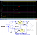
For your amusement, here's an LM317 circuit that uses a capacitively-coupled negative voltage circuit from a transformer supply, along with an LM337 to generate a -1.25V bias for the LM317 so its output can go to zero volts:
Note that it doesn't need a separate transformer winding for the negative voltage.

1786201249119.png
 
Last edited:

Thread Starter

jm-X

Joined Feb 12, 2023
29
For your amusement, here's an LM317 circuit that uses a capacitively-coupled negative voltage circuit from a transformer supply, along with an LM337 to generate a -1.25V bias for the LM317 so its output can go to zero volts:
Note that it doesn't need a separate transformer winding for the negative voltage.

View attachment 370045
Hi Crutschow,

Nice design, and thanks a lot for your two designs . Perfect.:)

My last question about my crude schematic:

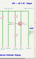
- is it a safe option, to add a TIP122 and voltage divider resistors to bias the base, if potentiometer is " blown "?
Useless or no sense ?

R4: 4.5 KOhm R5: 1 KOhm P: 0.6 W

I only want to avoid a voltage above 10 V DC to the drive.

So say 10 V DC Vb=1.82 V Vbe= 1.82 - 1.4 = 0.4 V TIP122 in cut-off mode? Right or Wrong?

9 V Vb=1.64 Vbe= 1.64 -1.4 = 0.24 V Same question as above. With Vbe 0.24 V I think it's off.

8 V Vb=1.45 Vbe = 1.45 -1.4 = 0 V I think i know the result!!!!!

TIP122-Resistors-Schematic.png


TIP122-Resistor.png


I forgot to say it: Nice day.

Jm
 
Last edited:

crutschow

Joined Mar 14, 2008
38,654
is it a safe option, to add a TIP122 and voltage divider resistors to bias the base, if potentiometer is " blown "?
Useless or no sense ?
----------------------------
I only want to avoid a voltage above 10 V DC to the drive.
Potentiometers seldom "blow" unless they are carrying excessive current.
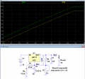
But it you just want to prevent the LM317 output from going above 10V output then you can add a 9V Zener or a TL431 2.5V adjustable reference with the appropriate resistor values to give a breakdown voltage of 8.75V, from the ADJ pin of the LM317 to ground.

Example below using a TL431, which gives a more accurate overvoltage limit:

1785677398790.png

If you want to prevent overvoltage due to an LM317 failure, then you can use a "crowbar circuit" which typically uses an SCR to clamp the output to ground and blow a fuse if the voltage exceeds the desired value.
 
Last edited:

Thread Starter

jm-X

Joined Feb 12, 2023
29
Potentiometers seldom "blow" unless they are carrying excessive current.
But it you just want to prevent the LM317 output from going above 10V output then you can add a 9V Zener or a TL431 2.5V adjustable reference with the appropriate resistor values to give a breakdown voltage of 8.75V, from the ADJ pin of the LM317 to ground.

Example below using a TL431, which gives a more accurate overvoltage limit:

View attachment 370065

If you want to prevent overvoltage due to an LM317 failure, then you can use a "crowbar circuit" which typically uses an SCR to clamp the output to ground and blow a fuse if the voltage exceeds the desired value.
Hi Crutschow,

Thanks for your replies, and schematics of course.

No, i have all i need for my PSU project, now Kicad.:):).

Thanks also to others members, doesn't matter their replies.

L'important c'est de participer Ethelbert Talbot then Pierre de Coubertin.

That's the way i like and not Huh, you are a beginner, Huh you are going to put two fingers or the whole hand in the plug, and Huh you are going to become a Christmas Tree.!!!!

Nice day.

Jm
 

Thread Starter

jm-X

Joined Feb 12, 2023
29
Istill do not understand the need for the complexity of the circuit in post #1. A single voltage regulator followed by an SCR crowbar overvoltage circuit will work quite well.
Hi MisterBill2,

Thank you for your reply and advice.

0 V to 10 V DC is needed, but for 18 V DC absolutely no need for 0 V DC; only 18 V DC +/- 1V say.

Nice day.

jm
 
IF, and ONLY IF, the system DOES NOT require a power source that can also sink current as well as source current, the simpler regulator systems can provide the needed variable voltages. AND, with the simple addition of a forward biased series diode in the positive line, the simple regulators can, mostly, provide down to zero volts. Thedownside is that adding that series diode prevents the supply from ever sinking any current, unlike a battery, or some regulated voltage supplies. So there is a trade-off.
 

Thread Starter

jm-X

Joined Feb 12, 2023
29
IF, and ONLY IF, the system DOES NOT require a power source that can also sink current as well as source current, the simpler regulator systems can provide the needed variable voltages. AND, with the simple addition of a forward biased series diode in the positive line, the simple regulators can, mostly, provide down to zero volts. Thedownside is that adding that series diode prevents the supply from ever sinking any current, unlike a battery, or some regulated voltage supplies. So there is a trade-off.
Hi MisterBill2,

Thank you first to send me a reply about this PSU.

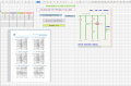
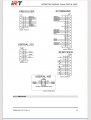
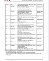
As you can see in the following data, my need is:

-Pin 2 SPEED IN + so +/- 10 V DC with a true 0 V DC
-Pin 3 SPEED IN - see above

Never seen a PMDC motor - or brushless given that commutator and slip rings are replaced by drive action -, stops at 1.25 V DC .....

As you know, and members of this forum are more seasoned than me, in Electronics Art, Vf is a funtion of If...

See, textbook on this site:

https://www.allaboutcircuits.com/te...chpt-3/introduction-to-diodes-and-rectifiers/

And of course the halt is mandatory, before reversing, or if you want to get a very huge back EMF, it's the way to follow
:mad:

- Pin 15 ENABLE 24 V DC
so here, no need for true 0 V DC i can also power supply with 24 V DC as 18 VDC is less than 24 ( safety margin ), but someone in a forum for CNC and DIY milling and others tools, told me it's better to get 24 V as with 18 V DC i can get errors.

- Pin 14 GROUND 24 V DC

IRT-Operating-Manual-p23.png


IRT-Operating-Manual-p25.png


Nice day for you and all forum members.

jm
 

MisterBill2

Joined Jan 23, 2018
27,936
There is a "cheap trick" to being able to reduce the output supplied voltage to zero, which is toadd an adequately rated diode in series with the output. As the supply voltage out drops below the diode forward voltage , the maximum current will be limited by the diode leakage current. At that point, a suitable voltage pilot light will shunt the current.
That trick is simple to try to verify that it is adequate.
 

crutschow

Joined Mar 14, 2008
38,654
There is a "cheap trick" to being able to reduce the output supplied voltage to zero, which is toadd an adequately rated diode in series with the output.
Already suggest by JHT in post #18.

Using that "cheap trick" for a LM317 with it's 1.25V minimum output, requires two diodes.
But then of course the output voltage would vary with the load current, and decrease about 4mV for every °C rise in temperature of the diodes due to dissipation and/or ambient temperature change.
Also the maximum output voltage would be reduced by those two diode drops.
 
Top