Facebook
 Google
 GitHub
 Linkedin
Hello all,
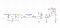
I continued the schematic for my project, which a power supply unit, 24V 4A.
These are the stages i have designed:
Common Mode Emi filter ( i know its not needed, but i chose to do so in order to learn ) i took example from other designs and calculated the cutoff frequency.
Transformer + Bridge Rectifier, which gives at the collector of each transistor, unregulated 30V voltage.
the drivery circuit, made with the OP AMP , the output of the op amp, which i calculated it to be around 24.7V
then with the formula VO=VZ*(1+R1/R2), i calculated R1 and R2, having Vz= 5.6 V and VOUT = 24 V
I took example from other designs, and they usually put a RE , emitter resistor of low value, which i did in the schematic.
I know that overall the circuit has not a lot of protection, like no Tvs or so, but beside that, is the concept correct?
The way i designed and calculated the sizing is correct for each component?
Thanks all for the help ( consider that im a newbie yet.. )
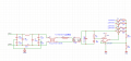
Attachments
-
 59.4 KB Views: 26
 .
.