when i complete this 555 positive trigger timer circuit , it is triggers from negative also, even touching with metal it also triggered. how to solve this
problem ,
Pins 2, 6 & 7 are all tied together? Not the expert on 555's but that strikes me as being incorrect. Also, pin 3 is tied back to pin 4 through R2. This also seems incorrect. I may be wrong, but - - - .
Pins 2, 6 & 7 are all tied together? Not the expert on 555's but that strikes me as being incorrect. Also, pin 3 is tied back to pin 4 through R2. This also seems incorrect. I may be wrong, but - - - .
Had a police sergeant come into an electronics outlet I was working at. He asked for a thing that plugs into the back of a thing and connects to another thing. Yes, that's exactly what he wanted and needed. He also said he didn't know what it was called. So I told him I don't know the name of it either. But we don't carry them. He could try another electronics shop in the next city over; and I sent him on his way.
A thing that plugs into a thing. Sad to say, we're going to need far more information than what you're providing. Detecting microwaves? Like leakage from a microwave oven? Like from a microwave gun? Microwave tower? All greatly differing topics. And guns is one of those prohibited subjects here. So if you're looking to make a microwave gun for some reason - you're not going to get an answer. In fact, without more information about what you have and want to accomplish, chances of gettin an answer are as likely as being able to teach a bear to fly an ultra-light.
Pins 2, 6 & 7 are all tied together? Not the expert on 555's but that strikes me as being incorrect. Also, pin 3 is tied back to pin 4 through R2. This also seems incorrect. I may be wrong, but - - - .
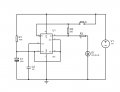
Below is the LTspice simulation of the circuit:
It acts as a one-shot, generating about a 11 second pulse at the output.
It's rather an interesting circuit and, somewhat surprisingly, all the connections make sense.
Before being triggered, the RST input is held low (Reset active) through the low OUT signal (Yellow trace) by R1, and the DIS pin keeps C1 (blue trace) at 0V.
Momentarily closing the SW (red trace) puts the RST high, which then allows the TRIG input to trigger the 555.
The causes the OUT to go high, which now keeps the RST high, independent of the switch position.
The DIS pin also opens, allowing C1 to charge through R2.
When C1 reaches the 555 THRS trigger voltage, the cycle is terminated, with the OUT going low along with the RST pin, and the DIS pin discharges C1.
 Facebook
 Google
 GitHub
 Linkedin