No, if using common ground.
How much current is needed on neg. supply ? For a few mA might use a 555 oscillator circuit to produce a neg. V, but + 5V
might be too low to give high enough neg. V to regulate. Use another 555 as V doubler or buy a boost-buck module with Neg. output?
You circuit has both inputs grounded. Here's a way to do what you want with the outputs having a common ground point.
It uses a special voltage regulator that can both sink and source current to allow a split voltage without adding a separate virtual ground circuit.
Only if you can guarantee that the positive current will never be more than the negative current, since that excess current has to flow into the output of the bottom regulator.
That's why I used a regulator that can both sink and source current.
Not as drawn. Each regulator has a 3.3 V output, so the input must be at least 6.6 V. But wait - each regulator has some headroom requirement, a minimum voltage drop from its input to output. If that is 0.5 V per regulator for example, then the minimum circuit input now is 7.6 V.
Only if you can guarantee that the positive current will never be more than the negative current, since that excess current has to flow into the output of the bottom regulator.
That's why I used a regulator that can both sink and source current.
I see. The 3.3V will also be used to power the MCU and other peripherals. The negative rail is only for the opamp. So yes the need to sink the excess current is evident. The original schematic had a dual secondary windings flyback transformer which was used to generate the negative rail. That transformer however is not available now. The LT1118 is fairly expensive in my part of the world. Any other replacements that are fairly inexpensive and easily available?
Not as drawn. Each regulator has a 3.3 V output, so the input must be at least 6.6 V. But wait - each regulator has some headroom requirement, a minimum voltage drop from its input to output. If that is 0.5 V per regulator for example, then the minimum circuit input now is 7.6 V.
Since you only need a small amount of current for the op amp negative voltage, you might consider using a switched-cap converter to generate the negative voltage from the positive voltage.
Linear Technology and others, sell such devices.
Since you only need a small amount of current for the op amp negative voltage, you might consider using a switched-cap converter to generate the negative voltage from the positive voltage.
Linear Technology and others, sell such devices.
I was just about to post on that. I found this chip which is fairly low cost and easily available - Microchip's TC7660S. I could use the +3.3V from the TLV1117-33 to generate a -3.3V just for the opamp here. That would work right?
I was just about to post on that. I found this chip which is fairly low cost and easily available - Microchip's TC7660S. I could use the +3.3V from the TLV1117-33 to generate a -3.3V just for the opamp here. That would work right?
That should work as long as the negative current is no more than a few mA [see Figure 2-7 in the data sheet which shows output voltage versus load (for various values of input voltage at the zero current point)].
That should work as long as the negative current is no more than a few mA [see Figure 2-7 in the data sheet which shows output voltage versus load (for various values of input voltage at the zero current point)].
Got it. This would power a LMV324M low power version of the 324. That datasheet lists the supply current as 410 uA. Thanks again for all your suggestions
Got it. This would power a LMV324M low power version of the 324. That datasheet lists the supply current as 410 uA. Thanks again for all your suggestions
Got it. The output will eventually feed into an MCU. Considering that the TC7660S can drive upto 20mA of negative load current and the opamps are consuming uA's of current, there is plenty of leeway. I'll do some testing though.
 Facebook
 Google
 GitHub
 Linkedin
 7.4 KB Views: 33
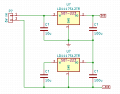
")


