Port from Arduino Uno to ATtiny85 240429

Thread Starter

allenpitts

Joined Feb 26, 2011
182
Hello AAC forum,

Working on using PIR & switch to operate
an Adafruit Neopixel Ring 24.
https://www.adafruit.com/product/1586

To get started it was decided to keep things simple.
1. If the switch is open the Neopixel is solid blue.
2. If the switch is closed the Neopixel is off, unless the
PIR is triggered. If the switch is closed
and the PIR is triggered the Neopixel is solid green
for an interval of time.

A sketch was written and loaded onto the
Arduino Uno and the system works well as designed.
Eos_Neopixel_2_color_240425_KB.ino, attached.

The Arduino setup is shown at
Arduino_setup_240426.jpg, attached
Arduino_setup_240426.jpg

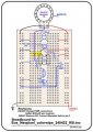
To make the system smaller an ATtiny85 was
substituted for the Uno using the breadboard
as shown in the attached line drawing
EOS__LED3_PIR_SW_NeoPix_240423_Brdbrd.jpg.
EOS__LED3_PIR_SW_NeoPix_240423_Brdbrd.jpg

But as shown in Test 240426.1 and
Test 240426.2, copied herewith below,
the sketch works perfectly on the Uno
but does not work on the breadboard.

So either the assumption that a sketch
that works on an Arduino Uno
will also work on an ATtiny is false
or
there is a defect in the breadboard
setup.

Please accept a request to review
and help me figure if one or
both of these premises is true.

Thanks

Allen Pitts

***** Test Results *****
Test 240426.1 ATtiny85, PIR & switch


Preconditions
1. Set up EOS__LED3_PIR_SW_NeoPix_240423_Brdbrd.jpg.
2. Load Eos_Neopixel_2_color_240425_KB.ino with Internal Clock to 8MHZ
3. SW1 open.

Action 1: +5v Power to board

Expected Result:
1. All Neopixel lights green constantly.
2. LED3 oscillates at 500 ms intervals.

Actual Result:
1. Neopixel does not light
2. LED3 lights constantly

Note: With the conjecture that the PIR is failing, a measurement
was done at PIR out/pin 7.
Result: 3.2 volts for eight seconds when PIR triggered.
Then 1.5 volts until PIR retriggered. Retrigger: 3.2 volts for eight seconds.
This is as expected.

Action 2: Move SW1 from open to closed
Result: 2.1. Neopixel, no change
2.2 LED3 off

Action 3: Move SW1 from closed to open
Result: 3.1. Neopixel, no change
2.2 LED3 on

Action 4: Move SW1 from closed t open
Result: 4.1. Neopixel, no change
4.2 LED3 off

Test 240426.2 Arduino Uno, PIR & switch
Preconditions
1. Set up EOS_Arduino_Setup_240426.jpg.
2. Load Eos_Neopixel_2_color_240425_KB.ino with Internal Clock to 8MHZ
3. SW1 open.
4. PIR isolated.

Action 1: +5v Power to board

Expected Result:
1. All Neopixel lights blue
2. LED3 oscillates at 500 ms intervals.

Actual Result:
1. All Neopixel lights blue
2. LED3 oscillates at 500 ms intervals.

Action 2: Wait 30 seconds for PIR LOW

Expected Result:
1. All Neopixel off
2. LED3 oscillates at 500 ms intervals.

Actual Result:
1. All Neopixel off
2. LED3 oscillates at 500 ms intervals.

Action 3: Retrigger PIR

Expected Result:
1. All Neopixel lights blue
2. LED3 oscillates at 500 ms intervals.

Actual Result:
1. All Neopixel lights blue
2. LED3 oscillates at 500 ms intervals.
 

Attachments

Dave Lowther

Joined Sep 8, 2016
332
I don't see a 100nF decoupling capacitor between pins 4 and 8. There should be one with short connections. E.g. if you have a 100nF with long enough leads you could plug it into the two holes marked in red with the cap spanning the chip.
1714472259112.png
I doubt that's causing the problem, but there should be such a decoupling capacitor and it won't do any harm to add one.
If I had this problem I'd go back and start with something simple such as flashing an LED and check that it works and the flash timing is as expected. Then depending on the result either fix the problem with the simple program or add more of your final code one part at a time and test at each stage
 

Dave Lowther

Joined Sep 8, 2016
332
So either the assumption that a sketch that works on an Arduino Uno will also work on an ATtiny is false
In general that is false. Some specific reasons that would make it false are:
  • The sketch may be using some hardware feature on the ATmega328p that doesn't exist, or is different on the ATtiny85
  • There may not be enough memory to run the sketch on the ATtiny85 (512B RAM). The ATmega328p has 2KB RAM
  • One or more libraries used may not support ATtiny85
  • Clock speed differences
In the small amount of time I spent checking, I couldn't convince myself whether or not the Neopixel library you are using supports the ATtiny85. I also couldn't be sure about your clock speed settings as I don't know how you have the fuses set.
or there is a defect in the breadboard setup
At the moment it's not either or, because both the ATtiny85 compatibility and the breadboard setup could be causing problems
 
Last edited:

Irving

Joined Jan 30, 2016
4,996
Adafruit Neopixel library is supported on ATtiny85 at least in the latest v1.12

Pinouts in code appear to tie up with breadboard...

Code compiles OK with plenty of space to spare

Program uploads with USBasp programmer OK.

I don't have a neopixel, but connected PB4 to scope

power on...

LED flashes at 1Hz
Burst of activity on PB4, followed by another 9.5ec later clock rate 800kHz approx.
Activity continues at 9 - 10 sec intervals

Press sw1
LED carries on flashing
Another burst of activity, followed by another when switch released... then at 9 - 10sec intervals...

I've not looked at code yet...
 

Dave Lowther

Joined Sep 8, 2016
332
breadboard setup.
I started out learning how to use the ATtiny85 on a breadboard just like you. I soon got fed up with the breadboard being a bit inconvenient. So I built the board shown in the attached pdf. Depending on how much work you are intending to do with ATtiny85s it may be worthwhile building something similar.
 

Attachments

Dave Lowther

Joined Sep 8, 2016
332
Is this "Vero wire" is enamelled wire?
It is coated with thin insulation that vaporises when soldered. See this link for more info.
And what is this transparent thing? That holds the wires
They are called combs. See this link for more info.
Also what about the pricing and availability of Atmel chips nowadays?
I've not bought any for a long time as I have plenty in stock. It seems like there is no problem with availability of ATtiny85 here for example.
 

Irving

Joined Jan 30, 2016
4,996
Wire-wrapping! I was using it back in the 1980's, thought it had gone the way of the dodo! £70 for the manual tool o_O, I'm sure I've got a couple knocking about somewhere in an old toolbox...
 

Thread Starter

allenpitts

Joined Feb 26, 2011
182
Hello Dave Lowther, Irving, KeithWalker and the AAC forum,

Based on suggestions from the excellent folks named in the salutation
two changes have been tested.

1. Added 100uF cap between Attiny85 pin 4 and pin 8
Test result: no change

2. Added 430 ohm pullup resistor between the switch Attiny85 pin 5.
Test result: LED3 oscillates as before, first three one second intervals
then .1 second intervals. The Neopixel does not come on.

Removed the 430 ohm pullup resistor between the switch Attiny85 pin 5.
and reconnected the switch directly to pin 5.
Test result: LED3 oscillates as before, first three one second intervals
then .1 second intervals. After the third LED3 toggle the Neopixel
lights solid green.

Tried adding and removing the pullup as 330 ohm and 470 resistors several times with
consistent results.

Powering the system with the switch open is less responsive. That is,
LED3 comes on but does not oscillate and the Neopixel will
not come on.

Thanks.

Allen
 

Dave Lowther

Joined Sep 8, 2016
332
2. Load Eos_Neopixel_2_color_240425_KB.ino with Internal Clock to 8MHZ
Are you sure the internal clock is set to 8MHz?
I just got a new ATtiny85 and downloaded a blink sketch to it. Using the AVR programmer shown in my previous attachment
delay(time) was taking 8xtime because it was running on 1MHz internal clock.
These are my settings (IDE 1.8.13):
1714658309733.png
Either I forgot, or just discovered, that the "Clock" setting highlighted in yellow doesn't set the clock to 8MHz. After doing "Burn Bootloader" highlighted in green, delay() works as expected.
 

Irving

Joined Jan 30, 2016
4,996
Yes, mine is definitely 8MHz. The code won't compile with 1MHz setting, as you cant generate a neopixel datastream at 800kHz with a clock that slow
 

Dave Lowther

Joined Sep 8, 2016
332
Test 240426.1 ATtiny85, PIR & switch

Preconditions
1. Set up EOS__LED3_PIR_SW_NeoPix_240423_Brdbrd.jpg.
2. Load Eos_Neopixel_2_color_240425_KB.ino with Internal Clock to 8MHZ
3. SW1 open.

Action 1: +5v Power to board

Expected Result:
1. All Neopixel lights green constantly.
2. LED3 oscillates at 500 ms intervals.

Actual Result:
1. Neopixel does not light
2. LED3 lights constantly
I tried this on my ATtiny85 and LED3 flashes at ~1Hz (500ms off + 500ms on). Measured 30 cycles with a stopwatch and it was near enough.
I checked my switch was wired correctly by adding a temporary line of code at the start of runLed3() that read the switch and returned immediately if it was pressed (LOW). Whilst the switch was pressed the LED didn't change state. I then removed the temporary line of code.
I haven't connected anything to the PIR pin so it is an unknown state.
I don't have any Neopixels to connect.
The LED continues to flash at 1Hz regardless of whether the switch is pressed or not.
This seems to be working better than your test results above where the LED is constantly lit.
Perhaps try removing the PIR and Neopixel connections and see if that makes the LED work correctly?
Like I said in an earlier post it's usually good to check things by getting something simple working and adding to it. It's much easier to go from working and add stuff until it stops working, than to try and find out why it's not working when we can't even do printf debugging.
[Edit added the following text] Let me know if there's anything else you would like me to try here
 
Last edited:

Dave Lowther

Joined Sep 8, 2016
332
Yes, mine is definitely 8MHz. The code won't compile with 1MHz setting, as you cant generate a neopixel datastream at 800kHz with a clock that slow
I had it set to 8MHz when I compiled / downloaded, but that didn't change the internal clock to 8MHz. The internal clock only changed to 8MHz when I did "Burn Bootloader"
 

Dave Lowther

Joined Sep 8, 2016
332
Hmmm, I'm not using bootloader, but this chip previously had one loaded...
I'm not using the bootloader either. I Googled to find out how to set the internal clock speed from the IDE and the answer was burn the bootloader. I'm assuming that as soon as I downloaded the sketch with the AVR programmer it overwrote the bootloader at this step:
1714665607740.png
[Edit added: That assumption seems to be valid because there's no noticeable delay between hitting the reset button and the LED starting to flash]
I could have spent some time re-learning how to set fuses with avrdude, but I was trying to save time. It's so annoying when stuff that was very familiar and easy a few years ago is a mystery today. I'm glad that I kept good notes from back then which I could follow. My blink sketch had delay(125) in it rather than delay(1000) but the comment said 1 second. Maybe I never did work out how to do it from the Arduino IDE. Most of my work with ATtiny85 was done with Atmel Studio because it supported the Atmel ICE which I was using to learn / debug AVR asm and how to use the ATtiny85 h/w peripherals.
 
Last edited:

Irving

Joined Jan 30, 2016
4,996
OK, I set pixels to 1 to maker it easier to see...

Power up generates an RGB of (0,0,0) at 9.6sec intervals

Pressing SW1 often generates RGB of (0, 0x31, 0) [assuming it transmits as GRB] reverting to (0, 0, 0) 19 sec later. This isn't consistent, sometimes the press generates (0, 0, 0) immediately. I suspect a contact bounce issue, you may need to time the checks for the relationship of currentSwitchValue and switchIsClosed.

Addendum: putting a 10k resistor to Vdd instead of relying on internal pull-up made this much more robust. Press gives (0, 0x31, 0) 55-65uS later, release gives (0, 0, 0) 45-55uS later. Sometimes you get contact bounce on the release, which generates three packets, (0, 0, 0), (0, 0, 0), and (0, 0, 0x32), 370uS apart.

Activating the PIR, PB2 going HIGH sometimes generates a (0, 0, 0x32) packet 65uS later. Pressing SW1 while PIR active generates a (0, 0, 0).

Not sure if that helps...
 
Top