 Facebook
 Google
 GitHub
 Linkedin
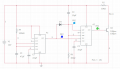
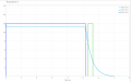
If someone(s) would please critique my pulse circuit below, I would appreciate it. The simulated output using generic parts from the simulator is good, hopefully real parts will be close. The goal is; upon powering up a 5-ish second delay then pull the net Pin-4 (at Q1) low for 0.5-ish seconds. The purpose of the circuit is to electrically "push a button" on a car dashboard (by pulling Pin-4 low) after the driver starts the engine. The 5 second delay is to allow the electronics in the car to fully boot before pushing the button. I'll likely use a 556 instead of the pair of 555's, but I'm very open to suggestions for something better.
The power source is a bit of a black box (the car schematic is short on details) but could be a pin from the ECU, so low power consumption is important. The net Pin-4 is an ECU pin pulled-up by an unknown pull-up resistor (estimated by R1 here), so I'm using a mosfet to pull it down.


The power source is a bit of a black box (the car schematic is short on details) but could be a pin from the ECU, so low power consumption is important. The net Pin-4 is an ECU pin pulled-up by an unknown pull-up resistor (estimated by R1 here), so I'm using a mosfet to pull it down.
Attachments
-
 54.7 KB Views: 3
 -
 30.3 KB Views: 3


