Play a tone PIC 16F628

Thread Starter

nerdegutta

Joined Dec 15, 2009
2,689
Hi,

I have a pic 16F628 circuit, and when a button is pressed, it triggers a relay.

Now I want to add a new feature; when the time is out, I want a piezo to buzz for 2 seconds. I have a 555-timer based piezo buzzer, and when I connect it to the pic and reprogram it, it's making a buzz. Just as I want.

But isn't it possible to connect the piezo directly to the pic? I think I've read somewhere, and seen some source code about that, but now I cannot find it.

Anyone?
 

thatoneguy

Joined Feb 19, 2009
6,359
What language are you using?

make a pin high, wait 1ms, turn pin low, wait 1ms, repeat 250 times for a 1/2 second tone. Vary the times for different frequencies.
 

Thread Starter

nerdegutta

Joined Dec 15, 2009
2,689
Yeah, just as I thought, some info missing. :)

I'm using MPLAB and Hi tech C.

So by turning a pin "on and off" really fast makes a tone?

Rich (BB code):
for(i=0;i<250;i++)
{
pin high
delay_ms(1);
pin low
delay_ms(1);
}
Something like this?
 

thatoneguy

Joined Feb 19, 2009
6,359
That's a low tone, for a speaker. You may want to make a low pass filter on the output to smooth it out a bit. like a 100 ohm in series with output pin and maybe a 0.1uF cap from that resistor to ground. This makes the sound a tad "cleaner" on a dynamic speaker. If you are using a piezo, you may need to tweak the components to cut off under 20kHz.
 

Thread Starter

nerdegutta

Joined Dec 15, 2009
2,689
OK. I will let you know, by posting the result in this thread. I will do it in the evening on thursday the 25.11.10.:)
 

thatoneguy

Joined Feb 19, 2009
6,359
I'll be here. Include source code, schematic and board photos for completed projects area. This would be a good example for others getting going in PIC programming.

P.S. Try out BoostC! They have a ton of examples, and it is what I am most familiar with.
 

Markd77

Joined Sep 7, 2009
2,806
I'd recommend a resistor as the capacitance of a piezo is a lot higher than the 50pF recomendation for pin loading. It might cause overcurrent and possibly resetting. I can't figure out the maths to work out how big the resistor should be.
 

Thread Starter

nerdegutta

Joined Dec 15, 2009
2,689
Hi.

This circuit I'm planning to use in my new UV-exposure box. The software is just made as an example. I will use Port A as input, and Port B as output. RA6 is now set to light the LED for just 2 seconds. This will be the test button. RA7, RA5-RA0 will have different values, so with a switch, I'm able to change the trigger-port, and still just have two buttons. Test and on.

This is the software, so far:

Rich (BB code):
/* 
 
Program:        main.c 
Description:    Timer program for UV-box 
PIC:            16F628 
IDE:            MPLAB 
Compiler:        Hi - Tech C 
Date:            Nov 2010 
Author:            Jens Christoffersen 
web:            www.nerdegutta.org 
 
*/ 
 
#include <htc.h> 
#define _XTAL_FREQ 4000000 
 
/* Configuration */ 
 
__CONFIG    (WDTDIS & 
            PWRTEN & 
            MCLREN & 
            BOREN & 
            LVPDIS & 
            DATUNPROT & 
            UNPROTECT & 
            INTIO); 
 
/* Prototyping the functions */ 
void lightLED(); 
void beep(); 
 
/* Global variables */ 
unsigned char i; 
 
/* Functions */ 
void lightLED() 
{ 
    PORTB = 0b00000001; // Setting bit 0 to HIGH 
    __delay_ms(1000); 
    PORTB = 0b00000000; // Setting all bits to LOW 
} // end lightLED 
 
 
void beep() 
{ 
    for (i=0;i<250;i++) 
    { 
        PORTB = 0b00000010; // Setting bit 1 to HIGH 
        __delay_ms(1); 
        PORTB = 0b00000000; // Setting bit 1 to LOW 
        __delay_ms(1); 
    } // end for-loop 
} // end beep 
 
/* Main program */ 
void main() 
{ 
TRISA = 0b11111111;    // Setting all bits on port a to input 
TRISB = 0b00000000;    // Setting all bits on port b to output 
 
PORTA = 0b00000000; // Setting all bits on port a to LOW 
PORTB = 0b00000000;    // Setting all bits on port b to LOW 
 
CMCON = 0x07;    // Disabling the analogue comparators 
 
while (1) 
{ 
    if (RA6) 
        { 
        for(i=0;i<2;i++) // Create a delay for 2 minutes 
        { 
            lightLED(); 
        } // end for-loop 
        beep(); 
        break; 
        } // end if 
 
} // end while 
 
}  //end main
I have not yet implemented the other time procedures.

As you can see, I'm using the internal oscillator.

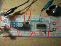
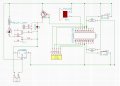
I've made a schematic, and taken a picture, see attachment. I'm not quite sure about the connections on the schematic. I made the breadboard first, then I drew the schematic. Yes, I know - A little backwards... :)

The piezo is connected to pin 7, and there is no resistor. I tried with some resistors, with different values, and the result was the volume of the beep. Haven't tried a speaker.

The powersource is for the moment a "jump-started" PC power supply. When I make the PCB I will include a .01uF and a 100uF capacitor over the LM7805.

Comments are welcome. :)
 

Attachments

Last edited:
Top