PIR sensor with 555 Timer

Thread Starter

allenpitts

Joined Feb 26, 2011
182
Hello AAC Forum,

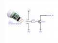
Have used this simple PIR circuit as the trigger for several timer, relay and transistor circuits
using the HC-SR501 sensor. Today working on a project that lights the treads on a staircase
where motion on a lower riser/tread turns on a LED on a tread above.
Simple_PIR_Circuit_200203.gif
So was looking to use a smaller PIR sensor and I happened on ordered
uxcell a15032000ux0258 Mini Pyroelectric PIR Sensor Module Model: AM312;
Manual Motion Infrared IR Detector


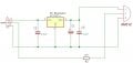
The circuit using the SR501 works perfectly
PIR_breadboard_sr501.JPG
But when the AM312 is plugged in
PIR_breadboard_am_312_300_x_400.jpg
there is no result.
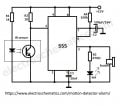
Obviously the AM 312 operates differently than the
SR501. So an attempt compare their operating
parameters. The SR501 has ample documentation.
SR501 datasheet

But the only thing listed on the Amazon page is
Package Content: 1 x PIR Sensor Module; Model: AM312; Main Color: White, Green
Working Voltage: DC 2.7-12V; Max. Static Current: 1mA; Delay Time: 2s
Blockade Time: 2s; Sensor Angle: 100 Degree; Sensor Distance: 3-5m
Working Temp: -20C to +60C; Total Size: 26 x 13mm/1" x 0.51"(L*D); Pin: 3

So here it is:
Has anybody worked with these mini PIRs AM312? They are all over the
internet, eBay and Amazon, but can't find a datasheet.

Thanks

Allen in Dallas
 

Attachments

Last edited:

Thread Starter

allenpitts

Joined Feb 26, 2011
182
Hello AAC forum,

Have a simple PIR circuit that works well.

Simple_PIR_Circuit_200203.gif
Have breaded board a 555 timer circuit that works
in monostable mode to send out a signal for about six seconds.
555-Timer-monostable-mode-circuit2.jpg
Working to get the signal from the PIR to trigger the 555.
PIR_to_555_monostable.jpg
Thee 555 timer circuit comes from
555 monostable

Can get both systems to work independently but not able to get the PIR to
trigger the 555.

Thanks.

Allen in Dallas
 

djsfantasi

Joined Apr 11, 2010
9,237
The PIR appears to have a high output when something is detected.

The 555 is triggered by a low (grounded) signal on the trigger pin.

The two signals aren’t the same. You need to modify the PIR output to produce a low/grounded signal when something is detected.

This is easy. You need to invert the signal. You could use a digital logic gate, but that’s more complicated than necessary. Driving an NPN BJT or an n-channel MOSFET will invert the signal for you. All with a couple of parts.
 

crutschow

Joined Mar 14, 2008
38,412
What does the PIR signal look like?

Note that to trigger the 555 requires a momentarily low (shorter than the desired output pulse width) signal (as generated in the first schematic).
You likely will have to add a transistor and capacitor coupling to get the proper trigger signal from the PIR.
 

prairiemystic

Joined Jun 5, 2018
425
PIR modules such as AM312, HC-SR505, HC-SR501 have a 3.3V voltage regulator on board, so their output is only to 3.3V which is not enough for a 555 timer running off 9V. You need something to level-translate. Also, the AM312 has a big output resistor R2 20k ohms so it cannot light an LED. I would add an extra transistor to the output, that to the 555 timer with 10k pullup resistor on TRIGGER pin 2 will work.
Just a note your 555 timing values, it's hard to get many minute delay times with the IC. Your 10k/460uF it maybe better to use bigger resistor say 1MEG. For many minute delays, look at CD4060 or CD4040.
 

Attachments

Last edited:

crutschow

Joined Mar 14, 2008
38,412
Below is the LTspice simulation of a 555 one-shot circuit with an added transistor to invert the trigger so that it will trigger from a 0-3.3V positive going pulse:
The trigger pulse can be longer than the one-shot period, without affecting the one-shot time.

1580791650355.png
 

TeeKay6

Joined Apr 20, 2019
573
Below is the LTspice simulation of a 555 one-shot circuit with an added transistor to invert the trigger so that it will trigger from a 0-3.3V positive going pulse:
The trigger pulse can be longer than the one-shot period, without affecting the one-shot time.

View attachment 198271
It won't change operation of your ckt, but the AM312 module that the T.S. is using claims to have an on-board 20K resistor in series with its output. That is, in your ckt V_PIR has an internal resistance of 20K.
 

Thread Starter

allenpitts

Joined Feb 26, 2011
182
Hello AAC forum

Thanks to djsfantasi, crutschow, prairiemystic and TeeKay6
for feedback on this project.

Based on that feedback six circuits were found on line which
approximate the intended function. GIFs of those circuits
and an analysis of their suitability is copied herewith below.

The winner was Motion-sensor-light-circuit.png
Motion-sensor-light-circuit_b.gif
This circuit was breadboarded successfully.
Observed monostable 555 periods using different values of C1 and R1
are also listed on the diagram marked 'PIR Sensor to 555 Monostable'.

The intent of the project is to light ten LEDS for about a minute
triggered by a signal from the PIR.

So the next step is to light more than one LED.
Motion-sensor-light-circuit_200210_w_extension.gif
First attempt is displayed in
'PIR Sensor to 555 Monostable w Extension LED'. No luck.

Second attempt shown in 'PIR Sensor to 555 Monostable w Extension LED'
ceased on the idea of using the 555 output to switch on power
to LED 2. No joy. Also tried connecting the transistor collector
to the cathode of the LED. Three for three.

So here I am again. What is done wrong. The data sheet on the
555 says it should operate a TTL and that the source/sink current
of the output pin is 200mA.

Why won't the output turn on more than one LED?

Thanks.

Allen in Dallas

+++200208++++
Of the five PIRs: Which one to bread board?
1. motion-detector-alarm.jpg: Second best
a. The output has a buzzer and a LED. The output
should be just enough to operate an NPN transistor
b. Uses a twelve volt power source
2. This the best one because:
a. The Trigger is connected to the PIR and
b. The values are on the schematic and
c. Its uses a nine volt power source
d. The output is a simple signal to an LED
3. The first evalution made this third best but the text
4. Circuit GIF taken from
The pictogram does not show the power source and,
because it is in Hindi it never indicates the value of the
power source.
5. 555_monostable_200124.jpg The Trigger pin 2 is connected to
the Threshold 6. Need for Trigger pin to be connected to the PIR.
6. Not clear how the PIR is connected to the Trigger. It looks
like the line marked 'V2' and 'pir' is the output signal from
the sensor but it not as clear as Motion-sensor-light-circuit.png.
Also, it has a twelve volt power source.as
The link to this circuit is found at the same forum thread on
https://www.electro-tech-online.com/threads/pir-sensor-and-555-timer.111491/
eclectro-tech-online forum as 3. NE-555-FIGURE28B.gif


+++200207++++
Comparing
1. motion-detector-alarm.jpg
2. Motion-sensor-light-circuit.png
3. NE-555-FIGURE28B.gif
4. You_tube_555_alarm_PIR_200206.gif
5. 555_monoastable_200124.jpg
6. 555_mono_1s_200208.gif

Pin 2 the trigger is connected to collector of an NPN transistor
and a resistor connected to the positive rail

Pin 3 is output and in You_tube is connected to an NPN transistor
that controls the load

Pin 4 reset is connected directly to voltage source

In all circuits except You_tube pin 5 is connected to ground
via a small value (.01uF) capacitor

Pin 6, threshold, in three circuits is connected directly to
pin 7. In two there is a medium resistor between 6 and 7

Pin 7, discharge is connected to ground via a capacitor
and to voltage via a 100k resistor


++++200206+++
https://www.electronicsforu.com/electronics-projects/hardware-diy/motion-detector-using-ne555-timer

https://www.instructables.com/id/Motion-Sensor-Activated-LED-Strip-With-Timer-1/


https://www.electro-tech-online.com/threads/pir-sensor-and-555-timer.111491/

http://www.unitechelectronics.com/NE-555-FIGURE28A.gif


Mouser Order Order Number: 18295606

You Tube
555 timer motion sensor
HOW TO MAKE MOTION DETECTOR ALARM

motion-detector-alarm.jpg
Motion-sensor-light-circuit.jpg
NE-555-FIGURE28A.gif
You_tube_555_alarm_PIR_200208.gif
555_monoastable_200124.jpg
 

Attachments

jbeng

Joined Sep 10, 2006
84
Hi Allen,
In the editor's note of your first drawing, it states "1000uF=1 Farad (I think)". That's incorrect, as 1000uF=0.001 Farad. As such, the time periods you measured are pretty close to what I calculate for the given values.

In your second drawing, the LEDs are connected in parallel with only one resistor. In a parallel arrangement, you should use a resistor for each LED. You can use one resistor if the LEDs are in series, however. At 9 volts, you should probably connect only three LEDs in series per string, but you can connect several of those strings to the 555 output pin.

The drawings 4 & 5 show the 555 configured for astable operation, which is a free running oscillator. I believe you're wanting monostable operation, also known as a one-shot. Your first drawings and the ones numbered 1,2 & 3 all show that configuation.

If I were building this circuit, I'd probably capacitively couple the PIR signal to the 555. That way, the trigger pin (pin 2) of the 555 is never held low for a long duration, as only pulses will pass thru the cap. Shown below is how I would likely do it. Your circuit already has the transistor with the resistor from collector to +9v; I would just add the cap & the second resistor.

Cap Coupled Inverter.gif
 

MisterBill2

Joined Jan 23, 2018
27,316
ALL of the commercially made PIR sensor heads made for security lighting that I have opened up included OP amp IC devices. So my first suggestion is to evaluate the output voltage of the new small sensor and know what you have as an input.It may be a voltage or it may be just a charge, or it may need a bias of some sort. And the information that you got with the amazon order is much more than I ever got on what I ordered.If you add an op amp you can get the gain that you need and also invert the sense of the signal to the 555 if that is needed. It is often very useful to start at the beginning with unknown parts.
 
I've continued working on this problem, but I've ditched the 555 timer due to it's power consumption. Below is something I've found online and modified a bit. This uses 0.01mA when "off", so it's extremely battery friendly. The LEDs stay fully powered for about a minute.

This uses 1 NPN transistor, 1 PNP transistor, various resistors, one electrolytic capacitor. There's two options for N-CH Enahancement MOSFET depending on input voltage.

20240128_163511.jpg
 

sghioto

Joined Dec 31, 2017
8,634
Nice but the LEDs are shown in the schematic reversed bias. The 100K resistor on the gate of the mosfet can be eliminated.
I like this circuit but how did you get 74 ma using two NE555 chips previously?
 
Last edited:
Nice but the LEDs are shown in the schematic reversed bias. The 100K resistor on the gate of the mosfet can be eliminated.
I like this circuit but how did you get 74 ma using two NE555 chips previously?

I'll fix the LEDs, good catch. Will remove the Moffett gate resistor too.

Yes, the previous post used a lot of power, it used two NE555s.

I've been trying to adapt this last drawing to only work in darkness. All my attempts actually result in higher amperage draw when off o_O
 
Last edited:

sghioto

Joined Dec 31, 2017
8,634
Why would that be?
Looking at the transistor circuit the current drain should be zero when not activated.
How much current does the PIR draw?
 
Top