Pic18f4550 LCD 4x20 not working

jayanthd

Joined Jul 4, 2015
945
tested options from 1 character to severel, never exeeded 20 ;)
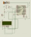
LCD never displayed anything till now? With or without LED code.

Zip and attach your project that doesn't work. (Complete MPLAB X XC8 project).

Attach your LCD datasheet here. Maybe it needs a little more delays in LCD_Init() routine for your LCD.
 
Last edited:

Thread Starter

Geid D

Joined Jun 28, 2015
36
now, apart lcd, i have only two additional lines that turn on the led.
usb works, bootloader works.

led lights on if i comment LCD_Print("MPLAB XC8"); line.
actualy as i wrote before, my code works if i remove data pointers from code (char*). if i call function (lcd_print) that has char* parameter, code dont work and led is off.

portB functions properly, i manualy latched every pin i use for LCD with leds.

my LCD model is 2004A
 

Attachments

Thread Starter

Geid D

Joined Jun 28, 2015
36
Vee is connected to +5 through 220R resistor, also Led+ pin which is not seen in schematic and LCD background shines... forget to add this to schematics...
 
Last edited:

ericgibbs

Joined Jan 29, 2010
18,766
OK, I suggested a check just in case the libs the program is using have not been written, expecting a high or low Port Byte connection.
 

Thread Starter

Geid D

Joined Jun 28, 2015
36
hi,
Did you get the opportunity to try a test run of the program with B7,6,5,4 [ B.4 in place of B.3].?
E
B4 is used for bootloaded. i checked portD also, but that didnt change the fact that program dont work if i call function with data pointer in parameted (char*).
 

Thread Starter

Geid D

Joined Jun 28, 2015
36
i wrote simple lcd test routine acording to datasheet Eric provided.
im excepting symbol "W" on LCD, but still no activity.
is my LCD initiation code correct?
Code:
#define _XTAL_FREQ 48000000
// CONFIG1L
#pragma config PLLDIV = 5       // PLL Prescaler Selection bits (Divide by 5 (20 MHz oscillator input))
#pragma config CPUDIV = OSC1_PLL2                                                                                                                                                                                                                                                                                                         // System Clock Postscaler Selection bits ([Primary Oscillator Src: /2][96 MHz PLL Src: /3])
#pragma config USBDIV = 2       // USB Clock Selection bit (used in Full-Speed USB mode only; UCFG:FSEN = 1) (USB clock source comes from the 96 MHz PLL divided by 2)

// CONFIG1H
#pragma config FOSC = HSPLL_HS  // Oscillator Selection bits (HS oscillator, PLL enabled (HSPLL))
#pragma config FCMEN = OFF      // Fail-Safe Clock Monitor Enable bit (Fail-Safe Clock Monitor disabled)
#pragma config IESO = OFF       // Internal/External Oscillator Switchover bit (Oscillator Switchover mode disabled)

// CONFIG2L
#pragma config PWRT = OFF       // Power-up Timer Enable bit (PWRT disabled)
#pragma config BOR = ON        // Brown-out Reset Enable bits (Brown-out Reset disabled in hardware and software)
#pragma config BORV = 3         // Brown-out Reset Voltage bits (Minimum setting 2.05V)
#pragma config VREGEN = OFF     // USB Voltage Regulator Enable bit (USB voltage regulator disabled)

// CONFIG2H
#pragma config WDT = OFF        // Watchdog Timer Enable bit (WDT disabled (control is placed on the SWDTEN bit))
#pragma config WDTPS = 32768    // Watchdog Timer Postscale Select bits (1:32768)

// CONFIG3H
#pragma config CCP2MX = ON      // CCP2 MUX bit (CCP2 input/output is multiplexed with RC1)
#pragma config PBADEN = OFF     // PORTB A/D Enable bit (PORTB<4:0> pins are configured as digital I/O on Reset)
#pragma config LPT1OSC = OFF    // Low-Power Timer 1 Oscillator Enable bit (Timer1 configured for higher power operation)
#pragma config MCLRE = OFF      // MCLR Pin Enable bit (RE3 input pin enabled; MCLR pin disabled)

// CONFIG4L
#pragma config STVREN = OFF     // Stack Full/Underflow Reset Enable bit (Stack full/underflow will not cause Reset)
#pragma config LVP = OFF        // Single-Supply ICSP Enable bit (Single-Supply ICSP disabled)
#pragma config ICPRT = OFF      // Dedicated In-Circuit Debug/Programming Port (ICPORT) Enable bit (ICPORT disabled)
#pragma config XINST = OFF      // Extended Instruction Set Enable bit (Instruction set extension and Indexed Addressing mode disabled (Legacy mode))

// CONFIG5L
#pragma config CP0 = OFF        // Code Protection bit (Block 0 (000800-001FFFh) is not code-protected)
#pragma config CP1 = OFF        // Code Protection bit (Block 1 (002000-003FFFh) is not code-protected)
#pragma config CP2 = OFF        // Code Protection bit (Block 2 (004000-005FFFh) is not code-protected)
#pragma config CP3 = OFF        // Code Protection bit (Block 3 (006000-007FFFh) is not code-protected)

// CONFIG5H
#pragma config CPB = OFF        // Boot Block Code Protection bit (Boot block (000000-0007FFh) is not code-protected)
#pragma config CPD = OFF        // Data EEPROM Code Protection bit (Data EEPROM is not code-protected)

// CONFIG6L
#pragma config WRT0 = OFF       // Write Protection bit (Block 0 (000800-001FFFh) is not write-protected)
#pragma config WRT1 = OFF       // Write Protection bit (Block 1 (002000-003FFFh) is not write-protected)
#pragma config WRT2 = OFF       // Write Protection bit (Block 2 (004000-005FFFh) is not write-protected)
#pragma config WRT3 = OFF       // Write Protection bit (Block 3 (006000-007FFFh) is not write-protected)

// CONFIG6H
#pragma config WRTC = OFF       // Configuration Register Write Protection bit (Configuration registers (300000-3000FFh) are not write-protected)
#pragma config WRTB = OFF       // Boot Block Write Protection bit (Boot block (000000-0007FFh) is not write-protected)
#pragma config WRTD = OFF       // Data EEPROM Write Protection bit (Data EEPROM is not write-protected)

// CONFIG7L
#pragma config EBTR0 = OFF      // Table Read Protection bit (Block 0 (000800-001FFFh) is not protected from table reads executed in other blocks)
#pragma config EBTR1 = OFF      // Table Read Protection bit (Block 1 (002000-003FFFh) is not protected from table reads executed in other blocks)
#pragma config EBTR2 = OFF      // Table Read Protection bit (Block 2 (004000-005FFFh) is not protected from table reads executed in other blocks)
#pragma config EBTR3 = OFF      // Table Read Protection bit (Block 3 (006000-007FFFh) is not protected from table reads executed in other blocks)

// CONFIG7H
#pragma config EBTRB = OFF      // Boot Block Table Read Protection bit (Boot block (000000-0007FFh) is not protected from table reads executed in other blocks)
// #pragma config statements should precede project file includes.
// Use project enums instead of #define for ON and OFF.

#include <xc.h>

#define LCD_RS LATBbits.LATB0
#define LCD_EN LATBbits.LATB2

#define LCD_D4 LATBbits.LATB3
#define LCD_D5 LATBbits.LATB5
#define LCD_D6 LATBbits.LATB6
#define LCD_D7 LATBbits.LATB7

#define LCD_RS_DIR TRISBbits.TRISB0
#define LCD_EN_DIR TRISBbits.TRISB2

#define LCD_D4_DIR TRISBbits.TRISB3
#define LCD_D5_DIR TRISBbits.TRISB5
#define LCD_D6_DIR TRISBbits.TRISB6
#define LCD_D7_DIR TRISBbits.TRISB7

void LCD_Strobe(void);

void main(void) {
   
__delay_ms(200);
TRISA = 0x00;
LATAbits.LATA5 = 0; // led off

LCD_RS_DIR = 0;           
LCD_EN_DIR = 0; 
LCD_D4_DIR = 0; 
LCD_D5_DIR = 0; 
LCD_D6_DIR = 0; 
LCD_D7_DIR = 0;
  
LCD_RS = 0;           
LCD_EN = 0; 
LCD_D4 = 0; 
LCD_D5 = 0; 
LCD_D6 = 0; 
LCD_D7 = 0; 
__delay_ms(30);
// Wake up call 1
LCD_D4 = 0; LCD_D5 = 0; LCD_D6 = 1; LCD_D7 = 1; LCD_Strobe();

// Wake up call 2
LCD_D4 = 0; LCD_D5 = 0; LCD_D6 = 1; LCD_D7 = 1; LCD_Strobe();

// Wake up call 3
LCD_D4 = 0; LCD_D5 = 0; LCD_D6 = 1; LCD_D7 = 1; LCD_Strobe();

// Function set 4 bit
LCD_D4 = 0; LCD_D5 = 0; LCD_D6 = 1; LCD_D7 = 0; LCD_Strobe();

// Function set 4 bit / 2 line - 5x10 font
LCD_D4 = 0; LCD_D5 = 0; LCD_D6 = 1; LCD_D7 = 0; LCD_Strobe();
LCD_D4 = 1; LCD_D5 = 1; LCD_D6 = 0; LCD_D7 = 0; LCD_Strobe();

// Display on curson on blink on
LCD_D4 = 0; LCD_D5 = 0; LCD_D6 = 0; LCD_D7 = 0; LCD_Strobe();
LCD_D4 = 1; LCD_D5 = 1; LCD_D6 = 1; LCD_D7 = 1; LCD_Strobe();

// Clear Display
LCD_D4 = 0; LCD_D5 = 0; LCD_D6 = 0; LCD_D7 = 0; LCD_Strobe();
LCD_D4 = 0; LCD_D5 = 0; LCD_D6 = 0; LCD_D7 = 1; LCD_Strobe();

// Entry mode set
LCD_D4 = 0; LCD_D5 = 0; LCD_D6 = 0; LCD_D7 = 0; LCD_Strobe();
LCD_D4 = 0; LCD_D5 = 1; LCD_D6 = 1; LCD_D7 = 1; LCD_Strobe(); // last 2 ?

// write "W character"

LCD_RS = 1; 

LCD_D4 = 0; LCD_D5 = 1; LCD_D6 = 0; LCD_D7 = 1; LCD_Strobe();
LCD_D4 = 0; LCD_D5 = 1; LCD_D6 = 1; LCD_D7 = 1; LCD_Strobe();

LCD_RS = 0;

// end of lcd test


LATAbits.LATA5 = 1; // led on

while (1) { // loop
}
   
}

void LCD_Strobe(void) { 
    LCD_EN = 1;                                             
    __delay_ms(100); // __delay_us(120);
    LCD_EN = 0;     
}
 

ericgibbs

Joined Jan 29, 2010
18,766
hi,
Looking thru the lib.c file, the line.
void LCD_Print(const char* LCD_Str)

Would it be correct to assume that it expects a Defined const char message, which should be pre Defined in the Header code.?
eg: 'pointer'
const unsigned char msg1 ="MPLAB XC8";

LCD_Print(msg1);

E
BTW: I am only a frequent user of 'C'.;)
 

Thread Starter

Geid D

Joined Jun 28, 2015
36
hi,
Looking thru the lib.c file, the line.
void LCD_Print(const char* LCD_Str)

Would it be correct to assume that it expects a Defined const char message, which should be pre Defined in the Header code.?
eg: 'pointer'
const unsigned char msg1 ="MPLAB XC8";

LCD_Print(msg1);

E
BTW: I am only a frequent user of 'C'.;)
originaly where was void LCD_Print(char* LCD_Str)
just tried various options :)
 

ericgibbs

Joined Jan 29, 2010
18,766
That code is in the LCD_Lib.C
clip from lib:

void LCD_Print(const char* LCD_Str)
{
uint8_t i = 0;
RS = 1;
while(LCD_Str != '\0')
{
LCD_Write_Nibble(LCD_Str >> 4);
LCD_Write_Nibble(LCD_Str[i++] );
}
}
 

Thread Starter

Geid D

Joined Jun 28, 2015
36
i tested about 4 or 5 different libraries. the point is that absence or exictence of CONST dont change things for me
 

Thread Starter

Geid D

Joined Jun 28, 2015
36
Is the VEE LCD pin connected to a pot like this:
https://www.pacificdisplay.com/lcd_cont_adj.htm
Adjust the pot and you should see black boxes where the chracters would be. Then adjut the pot so the black boxes almost disappear.
connected as shown now. in my case its white boxes (blue backlight) but strange that only 2nd and 4th line highlights when i turn knob and only near the end 1st and 3rd lines starts to apear. is that mean that lcd is broken?
 

AlbertHall

Joined Jun 4, 2014
12,345
It will probaly be near the end of the rotation of the pot but that is expected. Now turn the pot until the boxes nearly disappear.
 
Top