pic18f452 , PORTB

Thread Starter

ect_09

Joined May 6, 2012
180
Hello,
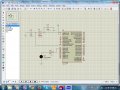
i am working in real time with PIC18f452. i try this code but confusion is here on the output.
Code:
#include<htc.h>


// PIC 18F452 fuse configuration:
// Config word 1 (Oscillator configuration)
// 40Mhz crystal input
__CONFIG(1, OSCSDIS & HSPLL);
// Config word 2
__CONFIG(2, BORDIS & PWRTDIS & WDTDIS);
// Config word 3
__CONFIG(3, CCP2RC1);
// Config word 4
__CONFIG(4, DEBUGEN & LVPEN & STVREN);
// Config word 5, 6 and 7 (protection configuration)
__CONFIG(5, UNPROTECT);
__CONFIG(6, WRTEN);
__CONFIG(7, TRU);

#define _XTAL_FREQ 40000000   //MHz

void delay_sec(unsigned char seconds)    // This function provides delay in terms of seconds
{
    unsigned char i,j;

    for(i=0;i<seconds;i++)
        for(j=0;j<100;j++)
            __delay_ms(10);
}

void main()
{
            
    TRISB = 0;     

    while(1)
    {
        PORTB = 0x55;       
        delay_sec(1);   // delay of one second

        PORTB = 0xAA;       
        delay_sec(1);    // delay of one second
    }
}
when i simulate this code in proteus then its shows all the blinking PINS of portb, but when i burn this code on PIC18f452 then RB0-RB4 blinking but RB5,RB6,RB7 not blinking...
what is its reason??? i also check the voltage these pins have 0 volt. please guide me in this way.

I also try this with
LATB= 0x55 ;
and
LATB= 0xAA;

Regards,
 

paulfjujo

Joined Mar 6, 2014
23
hello,

try to remove LVPEN in bits config
Low Voltage ICSP Programming (LVP) is enabled by default, which disables the RB5 I/O function.
LVP must be disabled to enable RB5 as an I/O pin


Code:
#include<htc.h>


// PIC 18F452 fuse configuration:
// Config word 1 (Oscillator configuration)
// 40Mhz crystal input
__CONFIG(1, OSCSDIS & HSPLL);
// Config word 2
__CONFIG(2, BORDIS & PWRTDIS & WDTDIS);
// Config word 3
__CONFIG(3, CCP2RC1);
// Config word 4
__CONFIG(4,STVREN);
// Config word 5, 6 and 7 (protection configuration)
__CONFIG(5, UNPROTECT);
__CONFIG(6, WRTEN);
__CONFIG(7, TRU);

#define _XTAL_FREQ 40000000   //MHz


void delay_sec(unsigned char seconds)    // This function provides delay in terms of seconds
{
    unsigned char i,j;

    for(i=0;i<seconds;i++)
    {
       for(j=0;j<100;j++) __delay_ms(10);
    }      
}

void main()
{
       
    TRISB = 0;    
    while(1)
    {
        LATB = 0x55;   // ->  0101 0101
        delay_sec(1);   // delay of one second
        LATB = 0xAA;    // ->  1010 1010    
        delay_sec(1);    // delay of one second
    }
}
 

atferrari

Joined Jan 6, 2004
4,764
Keep in mind that most of the settings are dedicated to peripherics. Let's say that the most "basic" is with all them off.

Interruptions aside, configuration was the major stumbling block I had in the past. Good luck.
 

Thread Starter

ect_09

Joined May 6, 2012
180
hello,

try to remove LVPEN in bits config
Low Voltage ICSP Programming (LVP) is enabled by default, which disables the RB5 I/O function.
LVP must be disabled to enable RB5 as an I/O pin


Code:
#include<htc.h>


// PIC 18F452 fuse configuration:
// Config word 1 (Oscillator configuration)
// 40Mhz crystal input
__CONFIG(1, OSCSDIS & HSPLL);
// Config word 2
__CONFIG(2, BORDIS & PWRTDIS & WDTDIS);
// Config word 3
__CONFIG(3, CCP2RC1);
// Config word 4
__CONFIG(4,STVREN);
// Config word 5, 6 and 7 (protection configuration)
__CONFIG(5, UNPROTECT);
__CONFIG(6, WRTEN);
__CONFIG(7, TRU);

#define _XTAL_FREQ 40000000   //MHz


void delay_sec(unsigned char seconds)    // This function provides delay in terms of seconds
{
    unsigned char i,j;

    for(i=0;i<seconds;i++)
    {
       for(j=0;j<100;j++) __delay_ms(10);
    }     
}

void main()
{
      
    TRISB = 0;   
    while(1)
    {
        LATB = 0x55;   // ->  0101 0101
        delay_sec(1);   // delay of one second
        LATB = 0xAA;    // ->  1010 1010   
        delay_sec(1);    // delay of one second
    }
}
with this code RB5 is not blinking but the other pins are blinking on real hardware..
what i do now..
 

tshuck

Joined Oct 18, 2012
3,534
with this code RB5 is not blinking but the other pins are blinking on real hardware..
what i do now..
Now you debug...

What value oscillator/crystal do you have attached?

What are your connections?

Post a schematic and a picture of your setup, and we can take a look..
 

Thread Starter

ect_09

Joined May 6, 2012
180
PIX is attached that i build up in my hardware..
why RB5 is showing 0 volt on its pin.???

circuitry is fine...working ok,
 

Attachments

tshuck

Joined Oct 18, 2012
3,534
PIX is attached that i build up in my hardware..
why RB5 is showing 0 volt on its pin.???

circuitry is fine...working ok,
What circuitry is fine: simulation or hardware?

The simulation layout looks fine, so, if it works in software, there is something with the hardware that should be examined...
 

Thread Starter

ect_09

Joined May 6, 2012
180
am working on hardware..
simulation shows all pins are working but on hardware RB5/PGM is not working...
:(
 

tshuck

Joined Oct 18, 2012
3,534
am working on hardware..
simulation shows all pins are working but on hardware RB5/PGM is not working...
:(
See page 94 in the datasheet.

Note 5 on a Table 9-3 says that with LVP enabled, RB5 is PGM and I/O functions are disabled...

Turn off LVP in the configuration bits.
 

tshuck

Joined Oct 18, 2012
3,534
Thanks , its working now...
Good to hear. This is why you must:
1. Read the datasheet
2. Understand that the simulation will not account for all of the nuances of a particular piece of hardware.

If the simulation works, look at your hardware and configuration settings.
 

Thread Starter

ect_09

Joined May 6, 2012
180
exactly, i ll start reading data sheet tomorrow.
sir please recommend me book to learn PIC18f. although data sheet is enough. but i really want to read the programming style too.
 

tshuck

Joined Oct 18, 2012
3,534
exactly, i ll start reading data sheet tomorrow.
sir please recommend me book to learn PIC18f. although data sheet is enough. but i really want to read the programming style too.
I have not seen a book I can really get behind. The last one I saw was so fraught with errors it was next to useless.

As you noted, the datasheet is what you need to have before you can effectively use a particular device.

Programming styles are a personal preference, for instance, I use the following style:
Code:
//any #includes

//function prototypes
void Initialize();

void main()
{
    Initialize ();

    while(1)
    {
        //do stuff

    }
}

//function implementations
void Initialize()
{
    //do initialization

}
Though another person may dislike that layout.

Look at plenty of examples of people having used the peripheral that you are attempting to use...
 
Last edited:
Top