PIC18F25K22 & 2 x 20 LCD

be80be

Joined Jul 5, 2008
2,395
The lcd code is made for the PICDEM2

The LCD is using the low nibble the library will have to be writing to use hi nibble

I'll rewrite it tonight
 

Attachments

spinnaker

Joined Oct 29, 2009
7,830
I tried your code, and it compiled just fine. But it still doesn't work.
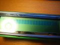
Now I got this.

I just can't see what's wrong.:(
This could be contrast. Do you have a pot on the contrast oin?

And I ask again. Did you physically verify each bit to the LCD. That is write a test program to toggle each bit.

Did you verify that your clock speed is what you think it is?
 

be80be

Joined Jul 5, 2008
2,395
It not contrast he has the LCD data hooked on RC4 to RC7

And the library he is using is for the lower bit of the port 0 to 3
 
Last edited:

MrChips

Joined Oct 2, 2009
35,122
This is a common symptom when the communications is not working (what else is there?).
I suggest we start from square one.

1) Can you provide the schematics for the interface? - MCU pinouts to LCD pinouts.
2) Verify the clock speed of the MCU.
3) Perform a basic toggle output port. If the speed exceeds the LCD specs the comm will fail.
4) Verify that the control lines are correct - RS, RW, E.
4) Check the LCD initialization procedure. You must switch to 4-bit mode. This must be done right otherwise it will not work.

(This is not a contrast problem since you can see the boxes on one line.)

I will be working on this sometime soon if you don't mind waiting.
 

be80be

Joined Jul 5, 2008
2,395
You all have no clue you didn't look at the code Hi-Tech C LCD sample Library is for the Lower bits of the PORT The code I posted will work if the OP hooks his LCD up as posted
in post 22 the Hi-Tech sampe was for the PICDEM2 it has data of the LCD on the lower port bits of RD0 to RD3

You can see it work here on hardware with my changes to code http://www.youtube.com/watch?v=Ly4yvi_-Vio


Thread Starter

nerdegutta

Joined Dec 15, 2009
2,689
This could be contrast. Do you have a pot on the contrast oin?

And I ask again. Did you physically verify each bit to the LCD. That is write a test program to toggle each bit.

Did you verify that your clock speed is what you think it is?
I got a pot on pin 3. and can adjust the contrast.
I've just verified by checking the wires is going to the right places. I don't have a scope - yet.


I suggest we start from square one.
I will get back to the drawing table, and provide a proper schematic. And datasheet for the LCD.

@be80be:
Your code compiled without errors or warnings.

Again - I'll make a proper schematic. (Which I should have done in the first place!!!)
 

be80be

Joined Jul 5, 2008
2,395
nerdegutta You'll never get this to work with the way it's going here

Your first post your code needed to set up the chips oscillator. I posted that you tried to compile it didn't that was because you left out delay.c

I posted you the whole project as I have which I no works I posted pictures and a video of it.

You have your hardware data pins wrong your using the upper 4 to7 just like i did when i said i was getting the same thing on my LCD

I then googled the PICDEM2 to see how there LCD was hooked up to the chip its on the lower bits 0 to 3 made a adapter for my board to change to RC0 to RC3 and code came on LCD worked find
I was going to fix the library to use upper pins but I didn't have time last night and after looking real good at it I think I would just write a new one so the LCD.h just handles int.
and the LCD.c just runs the code to work the LCD

But that will be later

Look at post 22 that's pic is right off the PICDEM2 witch is what the example you copied was wrote for works fine hooked up like that.

Just Use RC0 to RC3 the sch shows RD0 to 3 you can change ports but it has to still be lower 0 to 3 pins
 
Last edited:

Thread Starter

nerdegutta

Joined Dec 15, 2009
2,689
I will check into code and wiring. Make a schematic, and make code according to that.

Thanks for your effort and help.
 

Thread Starter

nerdegutta

Joined Dec 15, 2009
2,689
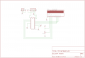
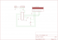
OK, so I've made a schematic, and tried be80be's code.

Schematic:

Click on image for bigger version

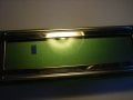
And now I got this:

It's one blinking cursor.

When I put a LED on the data pin, it flashes. When I put a LED on the control pin - nothing.

I've also tried to connect D4-D7 to RB0-RB3 - nothing.
 

Attachments

be80be

Joined Jul 5, 2008
2,395
You have registers to set to be digital like ANSELB has to be set to 0
ANSELB =0x0

Change your main code like this
Rich (BB code):
#include <htc.h>
#include <pic18f25k22.h>
#include "lcd.h"
#include "delay.h"

#define	XTAL_FREQ	4MHZ

void main(void){
    unsigned char pos=0x01, direction=0;
    ANSELA = 0x0;
    ANSELC = 0x0;
    ANSELB = 0x0;	
    OSCCON = 0x53;
    PORTA = 0x0;
    TRISA = 0x0;
    PORTB = 0x00;
    TRISB = 0x00;
    lcd_init(FOURBIT_MODE);
    lcd_puts("Bootloader demo !!!");
    
    while(1) {
	    direction?pos>>=1:pos<<=1;
	    if (pos==0x01 || pos==0x08)
	    	direction=!direction;
        PORTB = pos;
        DelayMs(100);
    }
}
 

Thread Starter

nerdegutta

Joined Dec 15, 2009
2,689
I was using MPLAB's settings, but changed it to this:

Rich (BB code):
#include <htc.h>
#include <pic18f25k22.h>
#include "lcd.h"
#include "delay.h"

#pragma config IESO = OFF, FOSC = INTIO67, PRICLKEN = OFF, PLLCFG = OFF


#define	XTAL_FREQ	4MHZ

void main(void){
    unsigned char pos=0x01, direction=0;
    ANSELA = 0x0;
    ANSELC = 0x0;
    ANSELB = 0x0;	
    OSCCON = 0x53;
    PORTA = 0x0;
    TRISA = 0x0;
    PORTB = 0x00;
    TRISB = 0x00;
    lcd_init(FOURBIT_MODE);
    lcd_puts("Bootloader demo !!!");
    
    while(1) {
	    direction?pos>>=1:pos<<=1;
	    if (pos==0x01 || pos==0x08)
	    	direction=!direction;
        PORTB = pos;
        DelayMs(100);
    }
}
Still nothing. Only cursor blinking on the 3'rd character.
 

t06afre

Joined May 11, 2009
5,934
Good for you. I'm starting to get so frustrated about this so I think I need to chop some fire wood!
Hmm I never saw a wild thing sorry for itself. A small bird will drop frozen dead from a bough without ever having felt sorry for itself
(David Herbert Lawrence)
 

be80be

Joined Jul 5, 2008
2,395
Try this to see if you can get the LCD to come on.

Export the configure make sure Pll is set off and the osc is set to INTIO67
Rich (BB code):
#include <htc.h>
#include <pic18f25k22.h>
#include "lcd.h"
#include "delay.h"

#define	XTAL_FREQ	4MHZ

void main(void){
   
    ANSELA = 0x0;
    ANSELC = 0x0;
    ANSELB = 0x0;	
    OSCCON = 0x53;
    PORTA = 0x0;
    TRISA = 0x0;
    PORTB = 0x00;
    TRISB = 0x00;
    lcd_init(FOURBIT_MODE); 
lcd_init(FOURBIT_MODE);
    
    
    while(1) {
		DelayMs(1000);
	    lcd_puts("Bootloader demo !!!");
        DelayMs(1000);
    }
}
 

Thread Starter

nerdegutta

Joined Dec 15, 2009
2,689
My code:
Rich (BB code):
#include <htc.h>
#include <pic18f25k22.h>
#include "lcd.h"
#include "delay.h"

#pragma config IESO = OFF, FOSC = INTIO67, PRICLKEN = OFF, PLLCFG = OFF


#define	XTAL_FREQ	4MHZ

void main(void){
    ANSELA = 0x0;
    ANSELC = 0x0;
    ANSELB = 0x0;	
    OSCCON = 0x53;
    PORTA = 0x0;
    TRISA = 0x0;
    PORTB = 0x00;
    TRISB = 0x00;
    lcd_init(FOURBIT_MODE);
     
    while(1) {
DelayMs(1000);
	lcd_puts("Bootloader demo");
DelayMs(1000);
        DelayMs(100);
    }
}
Cursor blinks on 3'rd character. No change.
 
Thread starter Similar threads Forum Replies Date
nerdegutta Microcontrollers 4
Similar threads
PIC18F25K22 & ADC problem
Top