PIC16F690 Potentiometers Shorting Out

Thread Starter

JDR04

Joined May 5, 2011
367
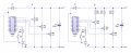
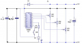
Hope somebody is kind enough to point out what I have done wrong here.

All this circuit does is flash an LED when the switch to PIN12 is pressed.

VR1 sets a delay time before the LED is allowed to come on.
VR2 sets how long the LED is allowed to stay on.
VR3 sets a time out period that prevents the LED from being set on again.

My problem is when I connect the pots up as in circuit A, they short/burn out when turned to the minimum.

I am wondering if I need to place a resistor from the 6V line to each pot as I have done in circuit B? Would this be correct or is there a better solution?

Thanks for the help....... JDR04
 

Attachments

olvine

Joined Mar 10, 2014
99
Why the supply voltage is 6V? Feed this 6V to a 5V voltage regulator....
and yes there is a chance that your code is not right.
 

John P

Joined Oct 14, 2008
2,068
I think most likely you've wired the pots using the wrong terminals, so that as far as the power supply is concerned, they look like a variable resistor rather than a constant one--and at its lowest, that variable resistor is zero ohms.

Also, don't put the feed to the potentiometers on the anode side of D1. That means that at the highest setting, the voltage sent to the A/D inputs would be higher than the processor's power supply, which means you can't measure it and it might cause problems with the input protection diodes. And, there should be a filter capacitor between pins 1 and 20 of the processor.
 

Thread Starter

JDR04

Joined May 5, 2011
367
Hi olvine, I thought if I use 6V but then use a diode I'd lose about 0.7V and that will bring the supply voltage to within the PIC's specification.

What do you think?
 

John P

Joined Oct 14, 2008
2,068
The chip's specs allow you to go to 5.5V (absolute max is 6.5) so the diode should work, if you really must run from a 6V supply. It isn't the best way to do things though.
 

enggricha

Joined May 17, 2014
89
Do update what the problem and the solution you arrived at...i am curious about this problem. If this was something to do with the PICs i would like to learn from ur experience.
 

Thread Starter

JDR04

Joined May 5, 2011
367
Hi folks, managed to sort the problem out by using a 10K resistor between the wiper and the microcontroller pin. Have run for over 24hrs now and pots are still cool, no evil wisps of white rising up from my bench and setting the smoke detector off!!!
 

THE_RB

Joined Feb 11, 2008
5,438
That is what we call a "bandaid" solution.

Your design is still bleeding to death, but now you put a bandaid on its wound so you don't see the blood. ;)

At least the actual fault seems to be a lot clearer now? :)
 

t06afre

Joined May 11, 2009
5,934
Hi folks, managed to sort the problem out by using a 10K resistor between the wiper and the microcontroller pin. Have run for over 24hrs now and pots are still cool, no evil wisps of white rising up from my bench and setting the smoke detector off!!!
That solution is kind of ouch!(shuddering)
I suggest you do something like this, like I told to do. I also noticed a flaw in your switch design. Then the switch is not active it will be floating. That is a no-no in digital design.
Edit the 10uF cap is kind of optional depending on how close it is to the 100uF cap
 

Attachments

Last edited:
Top