pic 18f2550 that resets

Thread Starter

kyu9971

Joined Mar 28, 2015
90
hi everyone.
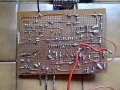
i am making an circuit with an pic 18f2550 for check the capacity of lead batteries.
for this purpose i use an 5v relais for to connect an load to battery and check the current and voltage.
i have an problem.
i maked the circuit in way that it can work in two mode.
mode one: with external power supply way usb
mode two: directally from the battery by to check.
when i use the circuit in first mode (with an external 5v power supply), it work is good.
when i use the circuit in second mode (directally from the battery to check, the pic is reset when the load to discharge the battery is connected.
you have some idea for solve this problem?
thank you
kyu9971
 

be80be

Joined Jul 5, 2008
2,072
It would be nice to see the circuit lot's of things could cause a reset.
The circuit would help to find out faster.
 

JohnInTX

Joined Jun 26, 2012
4,787
Is the BROWN OUT detector enabled in the config bits? The loaded battery may be dropping Vdd low enough to trigger it.
You could also be getting noise into MCLR/ when connecting the load.
 

Thread Starter

kyu9971

Joined Mar 28, 2015
90
thank you at all.
yes these are 12 volts lead acid batteries.
the load is an led light from 10w/12v (about 0.9 AH).
i have the circuit only on paper sheet and it is not much understandable, but if is necessary i post it.
i not understand because with an external power supply (ground in common).
i maked also other try.
i connected the load after the activation of the relais, but situation not change. when i connect the load the pic turning off and after turning on.
if i connect an simple little led (20 mA) then work is good.
as i can to eliminate any noise on MCLR (PIN 1).
i mounted two capacitor an 100nf beetween pin 20 an 19 and another capacitor from 470nf beetween pin 14 and ground.
maybe i should mounted some other capacitor but where?
maybe the capacitor that i mounted are much far to pic pins?
i attached some picture of my circuit.
 

Attachments

be80be

Joined Jul 5, 2008
2,072
You going to have problems you can't use pin 1 as your using it.
Need to see your configure setting the fuse setting.

But you can't use mclr as you have it.

Your trying to use the pin 1 it looks to be tied to 5 volts without a resistor and cap .
That pic nees MCLR more like this.
You don't have to use R1 .
But R 10K and C you should use.

The diode if your programming on the board don't hurt to have it.
But R and C are must have.
The 18f2550 is one chip I've used a bunch of I had 1500 of them
I loved that chip. lol
Screenshot from 2018-04-28 13-18-23.png
 
Last edited:

Thread Starter

kyu9971

Joined Mar 28, 2015
90
Hi,
Looking my circuit, you can tell me the value of these component?
R, R1, C.
i do not know very well this pic
thanks
 

Thread Starter

kyu9971

Joined Mar 28, 2015
90
Added the components to the circuit.

R1=2k2 (i have only this)
R=10k
C=100nf
D=1n4007

I have always the same issue.
 

ilkerhlm

Joined Apr 28, 2018
7
Last week i've made a rf toy car and i had the same issue, if there is peak current draw from whatever you use as supply , it can cause your microcontroller to reset. I used diode then parallel capacitor for the input to voltage regulator. I think the best way to solve this problem is try to measure feed voltage for microcontroller if theres not software caused problems.
 

Thread Starter

kyu9971

Joined Mar 28, 2015
90
Hi,
i assembled on breadboard an little circuit with the pic and its required components for to understand the issue.

I maked a little code for check the relais and its load.

With a pin i active the relais is and another pin i turn off the relais.

All to power supplied with a battery (12v 12Ah same used for the previous circuit)

It seems incredible!

On breadboard it is ok
I begin to connected the led light 5w,
after i added another led light10w,
after a stop light + day light (21w+5w) (car light)
And to the end i added one water pump (30w)

At this point i understood that the circuit have some problem, but i not understood where.


Naturally i tested the same simple code in the circuit of thread but here not work good
 

Attachments

JohnInTX

Joined Jun 26, 2012
4,787
Your wiring could be better. As it is, the PIC is getting power at the end of a bunch of wiring that also carries currents and noise for those heavy loads. Try cleaning it up.
A few things I'd try:
1) Separate the PIC power supply, Vdd and Vss, and bring the two wires back to the battery directly. Do not connect anything else to those wires.
2) Consider a dedicated 5V regulator for the PIC and the low level stuff, LCD etc. Locate it close to the chip and add filtering and decoupling to that dedicated PIC power supply. 1uF tantalum and .1 uf ceramic is a decent place to start.
3) Consider a bigger aluminum electrolytic 100uF or more on the input to the regulator as a stiffener - something to help hold to voltage up during startup surges caused by heavy loads.
4) Connect power and grounds for all of the other stuff back to the battery on their own set of wires. Don't share with the PIC except for a single point ground at the battery (-) terminal.
5) Consider writing test code that turns on each thing separately for a few seconds to ensure that all the drivers are OK. After that, turn on each load one at a time with a few seconds between. Monitor the PIC supply voltage while this is going on.
6) If you need to go further, read the RCON register and use temporary LEDs to display the various bits that show the reason for the RESET.
7) Explicitly disable the WDT and BrownOut Detector in the CONFIG bits.
8) Strap MCLR/ to Vdd to eliminate that as a source of resets while testing.
9) Be sure you have catch diodes across any DC coils and/or other transient suppressors as applicable. Even small coils can generate hundreds of volts when they release. You might need transient suppressors on the input to the PIC power as well if things are really ugly.
10) Make sure that pin 2 (AN0) of the PIC can never exceed Vdd, even as a transient. I don't know about that 6V zener...
11) Be sure all of your unused IO pins are set to digital and to output a '0'.

Just thinking out loud,
Good luck!
 
Last edited:

Thread Starter

kyu9971

Joined Mar 28, 2015
90
Hi johnln TX,
thank you for these suggestions.
i'm not very expert, but i readed with carefully your 11 points.

I searched to make a circuit on little board because i wanted to put it in little box (ex modem box), but if this not possible, i will change box and will make on board more big.

The circuit that i making, should have only 2 wire (medium size 2,5 mm2) to connect to the battery, red to positive and black to negative with 2 clamp.

Then i will must divide the supply inside the circuit.

Now, as you can se to my schematic, i have used an LM7805 that power supply all the components to 5 vdc (pic, relais, lcd, led power on, led load on, acs712, ds1307, external memory 24c32, lm35dz).

So i will use 2 voltage regulator one for pic, memory, ds1307, lcd...and another for relais, various leds, acs712.
i understod ok?

Could i to use more 78L05 (100 mA ), and divider the power supply?

I must put the 1uf tatalum and .1uf capacitor to the output of the and 100 uf electrolitic capacitor on the input of the voltage regulator dedicaded?

I used pin2 (AN0) of the pic as A/D converter for measured the battery voltage, but there is an voltage divider and the zener should be from 5v1.
anyway the battery is 12v and in this point the voltage does not exced 5v.

A questions is normal that when i connected the battery to the curcuit, there are the sparks on the terminals?

Kyu9971
 

JohnInTX

Joined Jun 26, 2012
4,787
OK. I do see from your schematic that you have the 470uF cap on the input of the 7805 and have proper caps on the input and output of the regulator. You also have some decoupling on the PIC. Good! I'd add a .1uf ceramic in parallel with the little electrolytic on the PIC power for transients.

I'd still separate the power lines to provide the PIC and its peripherals with their own power path to the power source. You mentioned using a separate 78L05 for the load devices. That might help.

There are a couple of ways to look at the power distribution that would change what I suggested above:

If you use one regulator, the distribution point is the regulator with lots of filtering. This means that the PIC and peripherals get a pair of power wires and the noisy stuff gets another pair of power wires and both are connected only at the power source - in this case the regulator. The idea is so that the PIC doesn't have to share noisy power/ground lines with other stuff.

You might consider another regulator for the noisy stuff. The connection would then be the inputs of both regulators get their own power wires back to the battery. The idea is the same, don't share noisy power lines with the PIC.

You mentioned you are using 78L05 regulators. Check your current loads carefully. It could be that as you add loads, the regulator is going into thermal shutdown. In a TO-92 package on a 12V source, they will go into thermal shutdown at around 80ma with a 30 degC ambient temp. As you add loads, they may be getting hot. Consider using a 7805 in a TO-220 package with a clip-on heat sink.

EDIT: Don't forget that many loads (motors, incandescent lamps etc.) draw much more power when starting up than when running. That could be a cause of power problems.

All of that should resolve any power problems. After that, I'd write that test code.

Good luck!
 
Last edited:

Thread Starter

kyu9971

Joined Mar 28, 2015
90
13052018639.jpg 12052018609.jpg 12052018612.jpg 14052018641.jpg 12052018634.jpg Hi everyone,
after two weeks i solved the issue on my circuit.
i followed the suggestions from JohnlnTX.
first thing i removed all power components line and i mounted them as far away as possible from microcontroller.
after i mounted the compontents near MCLR (diode, capacitor and 2 resiators) as data sheet.
at the last i mounted an fast diode and and an electrolitic capacitor on load.
now the circuit have not more issues.
i tried various differents loads also inductive and it work good.
thank you so much for your help.
i attached a new schematic and some picture of the finished project
kyou9971
 

Attachments

Last edited:
Top