pic 16F684

tshuck

Joined Oct 18, 2012
3,534
hello guys..i am now stuck after the following-

#INCLUDE <P16f684.INC>
__config _MCLRE_ON & _PWRTE_OFF & _WDT_OFF & _INTOSC & _CPD_OFF & _IESO_OFF & _CP_OFF & _BOD_OFF & _FCMEN_OFF

; ORG 0x000 ; processor reset

Initialise
bcf STATUS, RP0 ; activate BANK 0
clrf PORTA ; initialize PORT A
clrf PORTC ; initialize PORT C
movlw 0x07
movwf CMCON0 ; comparators OFF
bsf STATUS, RP0 ; change to BANK 1


how will i make my LED ON? should i create a delay?
and there is an instruction called Banksel? i dont know how to use it...please help me out!
Did you read the tutorial I linked? That goes over banksel and LED flashing...

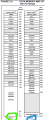
banksel selects the bank to use.. If you look at the memory organization of the PIC you are using, you'll notice this on page 10:


Notice there are two banks, and, for instance, TRISA is in bank 1, occupying the same address as PORTA in bank 0, 0x05. In order to set the direction of PORTA, the TRISA must be initialized to the proper state. So, you'd switch to bank 1, modify TRISA to your desired I/O configuration, and the switch back to bank 0 for PORTA I/O.
 

Attachments

Thread Starter

rp216

Joined Apr 5, 2013
20
please check this code

#INCLUDE <P16f684.INC>
__config _MCLRE_ON & _PWRTE_OFF & _WDT_OFF & _INTOSC & _CPD_OFF & _IESO_OFF & _CP_OFF & _BOD_OFF & _FCMEN_OFF

;ORG 0x000 ; processor reset
;movlw 0x07
;movwf CMCON0; comparators OFF

Initialise

bsf STATUS, RP0 ;select bank 1
movlw b'00000000' ;set PortC all outputs
movwf TRISC
movwf TRISA ;set PortA all outputs
bcf STATUS, RP0 ;select bank 0
clrf PORTA
clrf PORTC ;set all outputs low

Loop
bsf PORTC, 5 ;turn on RC5
call Delay ;this waits for a while!
bcf PORTC, 5 ;turn off RC5.
call Delay
goto Loop ;go back and do it again

Delay movlw d'250' ;delay 250 ms (4 MHz clock)
movwf count1
d1 movlw 0xC7
movwf counta
movlw 0x01
movwf countb
Delay_0
decfsz counta, f
goto $+2
decfsz countb, f
goto Delay_0

decfsz count1 ,f
goto d1
retlw 0x00

end


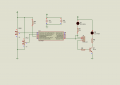
according to my circuit diagram

i think i need to borrow delay subroutines from other sites- im not sure of this one( marked in red)
 
Last edited:

Markd77

Joined Sep 7, 2009
2,806
Couple of things I spotted:
If you are using MCLRE_ON in the config then you need a 10K resistor from MCLR pin to 5V
You need a "return" in the delay function (which doesn't delay any noticeable amount of time).
You can find a better template in:
C:\Program Files\Microchip\MPASM Suite\Template\Code
 

absf

Joined Dec 29, 2010
1,968
Your program works fine in proteus after a minor modification. I uncommented the "org" and add the "equ" for the 3 variables used in the delay subroutine. I also added the 10K resistor to MCLR as suggested by Markd. The modified codes is here...

Rich (BB code):
#INCLUDE <P16f684.INC>
__config _MCLRE_ON & _PWRTE_OFF & _WDT_OFF & _INTOSC & _CPD_OFF & _IESO_OFF & _CP_OFF & _BOD_OFF & _FCMEN_OFF

count1	equ	0x20
counta	equ	0x21
countb	equ	0x22

	ORG 0x000 		; processor resets here
;	movlw 0x07
;	movwf CMCON0	; comparators OFF

Initialise

	bsf STATUS, RP0 ;select bank 1
	movlw b'00000000' ;set PortC all outputs
	movwf TRISC
	movwf TRISA ;set PortA all outputs
	bcf STATUS, RP0 ;select bank 0
	clrf PORTA
	clrf PORTC ;set all outputs low

Loop 
	bsf PORTC, 5 ;turn on RC5
	call Delay ;this waits for a while!
	bcf PORTC, 5 ;turn off RC5.
	call Delay
	goto Loop ;go back and do it again

Delay movlw d'250' ;delay 250 ms (4 MHz clock)
	movwf count1
d1 	movlw 0xC7
	movwf counta
	movlw 0x01
	movwf countb
Delay_0
	decfsz counta, f
	goto $+2
	decfsz countb, f
	goto Delay_0

	decfsz count1 ,f
	goto d1
	retlw 0x00

	end
Allen
 

Attachments

Thread Starter

rp216

Joined Apr 5, 2013
20
@ allen- i have already build my hardware circuit- i am using the internal master clear so hence it is not connected. should that be ok? i should only then change the instruction right?
 

absf

Joined Dec 29, 2010
1,968
@ allen- i have already build my hardware circuit- i am using the internal master clear so hence it is not connected. should that be ok? i should only then change the instruction right?
Looks like you didn't understand what Markd is saying:

If you are using MCLRE_ON in the config then you need a 10K resistor from MCLR pin to 5V
If you dont put in the 10K resistor, you PIC would not start unless you change your CONFIG to "MCLRE_OFF".

Allen
 

Markd77

Joined Sep 7, 2009
2,806
If you have pins to spare, and it looks like you do, I'd recommend using MCLRE_ON and the resistor.
It means you can easily reset it by connecting the pin to ground. It can sometimes be hard to reset PICs, because even if you disconnect the power pin they can draw power through an input pin and keep running, or if you pull power to the whole board sometimes the capacitor will keep them running for longer than you expect.
 

Thread Starter

rp216

Joined Apr 5, 2013
20
thanks guys! i now have to test that LED software with my hardware

should i now commence on the brightness control with the PWM? i will again go deep into the tutorial " tshuck" suggested. any tips on how i should progress on this?
 

Thread Starter

rp216

Joined Apr 5, 2013
20
i am still not getting it..i have used Y=MX + C equation for getting my duty cycle and my ADC value.

i found out y=4.01* X
where Y= PWM and X= ADC value

The frequency will be smallest when PR2 = 255 (maximum period)

for calculations is this ok?
 

Thread Starter

rp216

Joined Apr 5, 2013
20
programming the PWM part


values : PR2= 255
calculated period = 2.048ms
duty cycle = 9.76%
CCPR1L= 0.2ms
T2CON= 00000111
TRIS A= 00111100
TRIS C = 00011111


PWM
BSF STATUS,RP0
MOVLW B'00011111' ;Set RC5 as Output
MOVWF TRISC
MOVLW D'255'
MOVWF PR2 ;Place Value in PERIOD in PR2 Register
BCF STATUS,RP0
MOVLW B'00111100' ;Turn On PWM, P1A
MOVWF CCP1CON
MOVLW D'0.2ms' ;Place Decimal in CCPR1L Register
MOVWF CCPR1L
MOVLW B'00000111' ;Turn On Timer2, Prescale 1:16 & Postscale 1:1
MOVWF T2CON
BCF PIR1,TMR2IF


i am stuck. please help me out. i know i am making a mistake somewhere but i dont know where
 

tshuck

Joined Oct 18, 2012
3,534
I won't get a chance until tonight to look this over, but try reading page 84 in the datasheet. It gives you everything you need to do this...
 

tshuck

Joined Oct 18, 2012
3,534
Rich (BB code):
PWM
BSF STATUS,RP0
MOVLW B'00011111' ;Set RC5 as Output
MOVWF TRISC
MOVLW D'255' 
MOVWF PR2 ;Place Value in PERIOD in PR2 Register
BCF STATUS,RP0
MOVLW B'00111100' ;Turn On PWM, P1A
MOVWF CCP1CON
MOVLW D'0.2ms'[what!?] ;Place Decimal in CCPR1L Register
MOVWF CCPR1L
MOVLW B'00000111' ;Turn On Timer2, Prescale 1:16 & Postscale 1:1
MOVWF T2CON
BCF PIR1,TMR2IF
I'm not sure what you are trying to do. You have many different, conflicting values listed. What exactly are you trying to do for your test case?

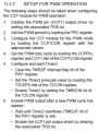
Your configuration is out of order according to the order specified on page 86:

You are setting RC5 to be output immediately. According to the specified order, you should set the corresponding bit and clear it only once everything is configured the way you want it.

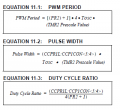
Have a look at the datasheet on page 85, you'll see the pertinent equations:


So, if you were using the default 4MHz internal oscillator, and wanting a 0.2ms pulse width(note, not the value in CCPR1L), you'd get:

0.0002ms/(16 * (1/4MHz)) = 50

So, (CCPR1L:CCPCON<5:4>) = 50 = 0x32, so CCPR1L = 50 >> 2 = 12 = 0x0C, and CCPCON<5:4> = 2 = 0b10.
 

Attachments

Thread Starter

rp216

Joined Apr 5, 2013
20
@ tshuck..i am trying to get a waveform for the PWM.

i am using a 8MHZ oscillator..internal oscillator.

duty cycle:-

CCP1CON- i have used value 00001111 for example

CCPR1L- i have used output as 100 -duty cycle

thus - 100x16x1/8mhz= 0.2ms

PWM PERIOD:-

prescale 16

period = (255+1) x 4x 16x(1/8MHz)= 2.048ms

percentage : 0.2/2.048 x100 = 9.76%

ok i made all port c values as outputs so it will be b'00000000'

** after finding this values i am very weak in programming. its not just clicking. i looked at the data sheets and the tutorials but im not just getting it.
 

tshuck

Joined Oct 18, 2012
3,534
the lowest two bits used for generating the PWM is in CCPCON, bits 5 and 4, so, to do the output you're wanting, you need to make CCPR1L = 100 >> 2 = 25, and CCP1CON<5:4> = 0....the least significant bits of 100.

Do you get a signal at all? Is the output there, just incorrect?
 

Thread Starter

rp216

Joined Apr 5, 2013
20
i didnt get your question..ok let me put it like this..

The subroutine sets CCPR1L to whatever is stored in a register called “Output”. Let us assume that “Output” = 100 then the duty cycle is 100x16x0.125 µs = 0.2 ms. So, as a percentage of the PWM PRF, the duty cycle is 100x0.2/2.048 = 9.76%.

The smallest duty cycle would be zero % (by setting CCP1CON to zero) and the largest would be when we set CCPR1L to 255 and set bits CCP1CON<5:4> to 11
 

tshuck

Joined Oct 18, 2012
3,534
i didnt get your question..ok let me put it like this..

The subroutine sets CCPR1L to whatever is stored in a register called “Output”. Let us assume that “Output” = 100 then the duty cycle is 100x16x0.125 µs = 0.2 ms. So, as a percentage of the PWM PRF, the duty cycle is 100x0.2/2.048 = 9.76%.

The smallest duty cycle would be zero % (by setting CCP1CON to zero) and the largest would be when we set CCPR1L to 255 and set bits CCP1CON<5:4> to 11
Again, this is not right.

The value in CCPR1L is concatenated with the two bits in CCP1CON, so that CCPR1L is the most significant 8 bits of what is used to calculate the PWM values.

The subroutine sets CCPR1L to whatever is stored in a register called “Output”. Let us assume that “Output” = 100 then the duty cycle is (100<< 2)x16x0.125 µs = 0.8 ms. So, as a percentage of the PWM PRF, the duty cycle is 100x0.8/2.048 = 39.06%.
or, if you want to do it faster, realize this is a counter(10-bit) and the duty cycle is 100% * (CCPR1L:CCP1CON<5:4>)/2^10 =(in this case) 100% * 400 / 1024 = 39.06%

Now, to my other question, are you getting a pulse-width modulated signal output at all?
 

Thread Starter

rp216

Joined Apr 5, 2013
20
i havent tested it out yet...i am still stuck with this values..my supervisor it doesnt matter if my PWm frequency is low..he just needs to see first my program and calculations.

i didnt get what you meant by " (100<< 2)".

electronics is really hard !
 
Top