you know what looking at it now..I have the 1K on the output of the 741 to the MOSFET Gate And looking at the 100K on pin 6 to ground but not on the gate of the MOSFET. If that makes any sense.
Once it is working, all you need to do is add a small touch of positive feedback to add hysteresis to the complete system so it doesn't toggle on/off when the light is on the borderline of the setting.
Using a pot to simulate the LDR and with an LED on the output, I can make it jitter with no feedback, 1M feedback, but not with 100k feedback. Not very scientific, but I think 100k is ok.
you know what looking at it now..I have the 1K on the output of the 741 to the MOSFET Gate And looking at the 100K on pin 6 to ground but not on the gate of the MOSFET. If that makes any sense.
Be sure that one end of the 100k is between the 1k and the gate, and the other end of the 100k goes to ground.
Note in the previous two posts that a 100k feedback resistor is a good addition. It goes from pin 6 to pin 3, and stops the op-amp from jittering while the light is just at the changeover point.
ETA: The 100k from the MOSFET's gate to ground is there to prevent exactly what you are experiencing, i.e., the MOSFET staying on all the time. I bet that fixing the pull-down fixes the problem.
Still not working! The MOSFET is showing 12 V on the gate but the Drain and source are all 0V.. I think the specs for the MOSFET needs something like 15V to turn on.. not 100% sure right now
*edit did not see your above post will check again
Still not working! The MOSFET is showing 12 V on the gate but the Drain and source are all 0V.. I think the specs for the MOSFET needs something like 15V to turn on.. not 100% sure right now
*edit did not see your above post will check again
I think the MOSFET will switch fine at 10 V. Remember that you have the MOSFET switching ground, so the source will always measure 0V, and the drain will measure 0V when the MOSFET is on. What is your power supply and what is its actual voltage? If it's 12.0 V, the high output on pin 6 should be a little less than 11 V and the low output about 1.3 V. Can you see the voltage change on pin 6?
I think the MOSFET will switch fine at 10 V. Remember that you have the MOSFET switching ground, so the source will always measure 0V, and the drain will measure 0V when the MOSFET is on. What is your power supply and what is its actual voltage? If it's 12.0 V, the high output on pin 6 should be a little less than 11 V and the low output about 1.3 V. Can you see the voltage change on pin 6?
I see no voltage change on pin 6 it's pretty much running the same voltage of the adapter in the whole circuit, i did the resistor like you said in the post above the 100K is between the 1K and gate.
I don't understand why something so simple is being confusing.
the funny thing is I thought it worked when i hooked it up because the light was not on So I covered the LDR and it came on but then pointed a flashlight at it and it was still on.
edit see another mistake I'm sure of it.. the LDR for some reason I don't think in it's current state the pot is controlling it.
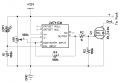
The whole idea is that there are two voltage dividers. The first one consists of the LDR and R1; the second is VR1 alone. Each of the voltage dividers has its output connected to the op-amp, which compares the voltages and makes pin 6 high when the resistance of LDR1 is high, and low when the resistance of LDR1 is low. When pin 6 is high, the MOSFET is turned on, which connects ground to the puck; +12V is permanently connected to the puck.
So, to troubleshoot the circuit, first make sure that your prototype is wired like the schematic.
Next, make sure that the LDR is at very high resistance (a few hundred thousand ohms) when it is dark and much lower resistance (50k or less) when it is light. You will have to lift one end of the LDR from the circuit in order to accurately measure it.
Next, make sure that pin 6 is low when the LDR's resistance is low. This is where you may need to adjust VR1. Put light on the LDR, and rotate VR1 until you see pin 6 go high, and then turn VR1 the opposite way so that pin 6 goes low. Then, cover the LDR so that it gets no light, which should cause pin 6 to go high.
Next, check the voltage on the gate of the MOSFET. You should see the same results as in the previous step. When the gate is high, you should see 0 V on the drain of the MOSFET, and since +12 V is permanently connected to the puck, it should provide power to the LED's.
At whatever point the results don't match what is supposed to happen, you have to determine what failed and fix it.
I think it's probably a wiring error, but it could be that the MOSFET you are using needs more current to turn on than the op-amp is supplying. I am not familiar with the MOSFET you are using.
The pot does not control the LDR; the LDR's resistance depends only on whether or not it is being lit. When the LDR is in the dark, its resistance is very high; when the LDR is being lit, its resistance is much lower.
now I have no light.. but now I can see on my scope no light gives me about 8 V and when light hits the LDR I get 12 V I still get no light when it does hit 12V.
I think I'm going to retire for the night have to be a work in 4 hours maybe tomorrow later I can think a bit clearer.
I was thinking here would it be better switching to the LM339 comparator? looking at the specs if it indeed is my supply is not enough the LM339 has a voltage input range of -0.5-36 VDC
Also tracecom did you get your 741 working on a single supply voltage? Most sites I see talk about it being connected to a dual supply voltage.
Depending upon the actual resistance values of the LDR you are using and the light conditions, you may have to change the value of R1 (on the schematic I posted.) Try it as 1k, 10k, 100k, and 1M and see which works best. Ideally, VR1 would be close to its midpoint at the switching point.
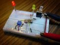
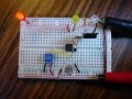
A couple of photos of my working breadboard are attached for whatever help they may be. The red LED indicates there is power to the breadboard. The yellow LED is on the op-amp output. The white LED is on the MOSFET's output. Note that I found that 1k was the optimum value for R1 with the LDR and the lighting conditions I am using. However, the circuit worked with a 100k for R1, but required that VR1 be at the very end of its range.
Depending upon the actual resistance values of the LDR you are using and the light conditions, you may have to change the value of R1 (on the schematic I posted.) Try it as 1k, 10k, 100k, and 1M and see which works best. Ideally, VR1 would be close to its midpoint at the switching point.
A couple of photos of my working breadboard are attached for whatever help they may be. The red LED indicates there is power to the breadboard. The yellow LED is on the op-amp output. The white LED is on the MOSFET's output. Note that I found that 1k was the optimum value for R1 with the LDR and the lighting conditions I am using. However, the circuit worked with a 100k for R1, but required that VR1 be at the very end of its range.
I think something must be wrong with the way my VR1 is connected As I said before I switched to the Lm339 and So the wiper is connected to Pin 7 and one lead to 12V and the other ground.. OK
So 2nd of all I think I need to reverse the resistor around because I get 12V with light on the LDR.. anyways my voltage on pin 6 & 7 are the same which is why it's not activating the output Pin 1 to turn on the Mosfet.

 Facebook
 Google
 GitHub
 Linkedin