photointerrupter with internal pull up

Thread Starter

Topad

Joined Nov 30, 2021
24
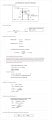
Hi All, Im looking to use this photointerrupter RPI-0451E. I have it with Foward Current about 11ma and VCC 5V. The output collector pin goes to a PIC18f4420 pin with internal pull up enable. In this from I get a logic level of 5v or 0v (0.23v). Using the treansitor as a switch. But reading more it looks this was a not good approched in the long run using the internal pull up on this photointerrupter was not okay and should have used an external pull up. I don't really care about timing just that the output goes from high logic to low logic. Looks like I IC collector current it need to be much more, even when is only been use as a switch to ground.

1729663035359.png
 

Attachments

BobTPH

Joined Jun 5, 2013
11,515
Determine the leakage current of the phototransistor and the sourced current if the internal pullup (from datasheets.) The pullup current must be much larger than the leakage current to get a valid logic output. If it is not, use an external pullup of 10K or so.
 

schmitt trigger

Joined Jul 12, 2010
2,086
Are you using the circuit as shown in YOUR shared image below?
If so, there lies the problem:

A pullup is a resistor to Vdd+
A pulldown, as shown in your image, is a resistor to ground.IMG_0348.jpeg
 

crutschow

Joined Mar 14, 2008
38,503
The circuit with the pullup in the collector, will invert the input to output voltage.
The circuit with the resistor to ground from the emitter will give a non-inverted signal.
Do you care which it is?
 

Thread Starter

Topad

Joined Nov 30, 2021
24
Determine the leakage current of the phototransistor and the sourced current if the internal pullup (from datasheets.) The pullup current must be much larger than the leakage current to get a valid logic output. If it is not, use an external pullup of 10K or so.
Hi Bob, by leakage current you mean the dark current on the datasheet they have 0.5 micoamps. The Pic datasheet states the weak pullup can deliver min 50 micro amps to 400 micro amps. I have measured and the typical is 200 mircoamps. I'm just don't seem to see how the Ic collector current will be the optimal and if I use 11ma foward current or more but it will degrade the led more quickly
 

Thread Starter

Topad

Joined Nov 30, 2021
24
The circuit with the pullup in the collector, will invert the input to output voltage.
The circuit with the resistor to ground from the emitter will give a non-inverted signal.
Do you care which it is?
Hi the pullup works okay. I firmware I just see the low as nothing present and high when there something blocking. But Don't care which it is. It works, but the datasheet don't show how to calculate the right IC for best results overtime, or I dont seem to underatand. Does this internal pullup is okay, or should bring the IC current more higher, but thay looks like increasing the foward current as well.I only found a calculation example in their Rohms website
 

BobTPH

Joined Jun 5, 2013
11,515
I'm just don't seem to see how the Ic collector current will be the optimal and if I use 11ma foward current or more but it will degrade the led more quickly
Yes, the dark current would be what I meant. Since it is way less than the oulluo current it should wok fine.

The 11mA LED current has nothing to do with it. I would use whatever the data-sheet recommends as the minimum. You could check the transfer ratio, but that would not be a problem at the low output current we are talking about. The transfer ratio tells you what percentage of the LED current can flow in the from collector to emitter. It will be way above the pullup current at the minimum recommended LED current.
 

Thread Starter

Topad

Joined Nov 30, 2021
24
@
BobTPH
crutschow


on the image, the photoint datasheet shows IC min .16 typ .45, but then on the other image I shared on their example calculations, they multiplied times half 0.5 to account for the 50% led reduction. I don't seem to understand the right approach with IC current. All I need is the act as a switch, but the cut off reagion seem to be very close based on the graphs they show1729715664053.png
 

crutschow

Joined Mar 14, 2008
38,503
the cut off reagion seem to be very close based on the graphs they show
Don't understand what you mean by that.
What is the "cut off region"?
Close to what?

The dark current is 0.6µa max, so the pull-up just has to supply sufficient current above that to pull the voltage up.
Thus, for example, a 1 MΩ pullup to 5V will give a high voltage of about 4.4V when the opto is off.
 

Thread Starter

Topad

Joined Nov 30, 2021
24
Don't understand what you mean by that.
What is the "cut off region"?
Close to what?

The dark current is 0.6µa max, so the pull-up just has to supply sufficient current above that to pull the voltage up.
Thus, for example, a 1 MΩ pullup to 5V will give a high voltage of about 4.4V when the opto is off.
I just don't seem to make a relationship between dark current and the IC min they mention like min 0.16ma to 0.45ma. Yes the dark current is like 0.05. The cut off region I mean lets say the pull up current passing through the transitor is 0.23ma but what if the current starts going down to lest say 0.10ma or less becuase maybe the led is life is reduced to maybe 70% which brings the current on the transitor down and thus approaching the "cut off region" and is not 0 to 5v but less maybe 3 to 5v. Not sure I'm explaining what I trying to say. I guess should I based calculations on dark current or IC min they show
 

BobTPH

Joined Jun 5, 2013
11,515
on the image, the photoint datasheet shows IC min .16 typ .45, but then on the other image
That is the transfer ratio, It says that if you supply the LED with 10mA, and there is 5V across the collector to emitter, at least .16mA will flow from C to E. This is a parameter for operation in the linear region. It has nothing to do with use in a switching application.

In a switching application, you want the Vce to be very small when the LED is on That is what the saturation characteristics are about.

The saturation spec says that with 10mA of LED current, and .1mA of collector current, the max voltage across CE is 0.4V. At the 200uA (.2mA) current with the weak pullup, it will be something more than 0.4V. Usually there is a chart that shows saturation voltage vs collector current. What you are interested in is what the saturation voltage is at 400 uA since that is listed as the max current the weak pullup will source. If that voltage is too high for it to be recognized as a logic low (highly unlikely) that would be a problem.
 

Thread Starter

Topad

Joined Nov 30, 2021
24
@BobTPH

Yes, they show this graph below. It loos like at 400uA the VCE will still be less than 1V more then than 400uA at IF=10ma VCE will go beyond 1v far from the 0.4 min saturation Vce. Is this the correct way to look it this graph? . So far it looks that using the internall pullup with from the mirco current from 50uA to 400uA would not be a problem at If=10-11ma and using the photointerrruper as a switch to get a low and high logic.

1730608476274.png
 
Top