PCB schematic symbols

Thread Starter

Artūrs Brīdaks

Joined Feb 19, 2017
8
Hello,

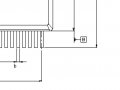
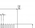
Currently, I am drawing SPV1020 PCB scheme in a KiCAD and I'm a little bit confused of the symbols included in the datasheet drawing. What does A (B, C, D etc.) in a box stands for? (Picture included)

Would appreciate any kind of help,
Thank you!
 

Attachments

dl324

Joined Mar 30, 2015
18,326
Welcome to AAC!

B looks like a dimension label. Same for A, except it may have a note. More context would help.
 

AlbertHall

Joined Jun 4, 2014
12,625
A, B and C in boxes seem to refer to something else, but the other letters are dimensions from the table on the previous page.
 

Thread Starter

Artūrs Brīdaks

Joined Feb 19, 2017
8
A, B and C in boxes seem to refer to something else, but the other letters are dimensions from the table on the previous page.
Okay. But how do I find the size of the case? E seems to be right for one side but what about the other? I thought that A could stand for that but apparently not. Anything else seems not to be bound to the other side.

Also, what about this little weird "letter"? (picture included)
 

Attachments

AlbertHall

Joined Jun 4, 2014
12,625
Above the case there is a 'mess' on the centre line - that is a 'D'
The weird letter you show is a lower case 'e'.
Not the best quality image I have ever seen. It is quite low resolution.
There is a better image here for a different chip although yours doesn't include the heatsink pads underneath.
 

Thread Starter

Artūrs Brīdaks

Joined Feb 19, 2017
8
Above the case there is a 'mess' on the centre line - that is a 'D'
The weird letter you show is a lower case 'e'.
Not the best quality image I have ever seen. It is quite low resolution.
There is a better image here for a different chip although yours doesn't include the heatsink pads underneath.
Thank you, Albert, for the link and everyone else who participated in this discussion. This will help me quite a lot!
 

dl324

Joined Mar 30, 2015
18,326
I think the capital letters with what look like arrows are viewing planes that don't mean anything to EEs who'll be reading the drawings.

'C' points to the view below it, 'A' points to the view above it, 'B' points to the view to the right of 'A'. As an EE, the drawing is simple enough that I could have figured that out without the 'pointers'.
upload_2017-2-19_7-47-19.png

That ST datasheet could have saved a page, and be easier to read, if they put the dimensions on the drawing instead of in a table on a different page:
TI 74HCT573
upload_2017-2-19_7-45-36.png
 
Top