Panasonic RE 6137 as Guitar Amplifier with Preamplifier

Thread Starter

Jsprite7660

Joined Jan 9, 2024
62
(This is a new thread on an old subject, as I have updated the previous project. Also, I am aware that this circuit isn't intended to be a guitar amp and people will suggest not doing it and doing a different conversion etc. I'm doing it for my own reasons so bare with me please and thank you for the help).

Hey All,

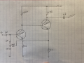
I converted a Panasonic RE6137 AM/FM radio into a guitar amplifier by first feeding the guitar signal through a preamp(photo below), and then into the volume pot of the radio. (No Isolation from Mains) It sounds fantastic

I now need to add an isolation transformer and have a Shure 51A303 from a Shure Sm57. The preamp itself is separately powered from the radio's circuit, so I could add the transformer after the preamp and still be isolated, but wasn't sure which was a better option.

Any thoughts?
 

Attachments

MrChips

Joined Oct 2, 2009
35,182
It is fine as long as you are not planning on using it with an electric guitar.
(For an AC powered guitar amp, it is critical that the amplifier is properly grounded to earth ground and that the guitar's ground is also connected to earth ground.)

For the pre-amp connected to the radio amplifier, you do not need a transformer. The output capacitor of the pre-amp is a DC blocking capacitor. Hence the signal is AC coupled to the radio.

If you wish galvanic isolation, you can use a linear opto-coupler or go RF.
 
I can barely see a 12V label on the output transistor's collector.
Why don't you use a 12VDC wall-wart supply, connect it across C25 (not sure exactly about the reference designator). Because this will be full-wave vs the actual half-wave, you will have lower hum and in addition it will be isolated from the line .
But I have a feeling that you would like to keep the original hot chassis and will dismiss the suggestion.
 
Last edited:

Thread Starter

Jsprite7660

Joined Jan 9, 2024
62
It is fine as long as you are not planning on using it with an electric guitar.
(For an AC powered guitar amp, it is critical that the amplifier is properly grounded to earth ground and that the guitar's ground is also connected to earth ground.)

For the pre-amp connected to the radio amplifier, you do not need a transformer. The output capacitor of the pre-amp is a DC blocking capacitor. Hence the signal is AC coupled to the radio.

If you wish galvanic isolation, you can use a linear opto-coupler or go RF.
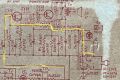
Ok I get the capacitors blocking DC and understand that after the diode, it's only DC. But in the photo below, can you explain how AC can't follow the yellow highlighted path back to the input?

Is it because of that polarized electrolytic capacitor right before the first transistor or the resistors pull it to zero? Just want to understand why, thanks.
 

Attachments

Thread Starter

Jsprite7660

Joined Jan 9, 2024
62
I can barely see a 12V label on the output transistor's collector.
Why don't you use a 12VDC wall-wart supply, connect it across C25 (not sure exactly about the reference designator). Because this will be full-wave vs the actual half-wave, you will have lower hum and in addition it will be isolated from the line .
But I have a feeling that you would like to keep the original hot chassis and will dismiss the suggestion.
Hey no, I appreciate that. Are you talking about powering the preamplifier with 12VDC? I am currently using a wall-wart for that. If that's what you mean
 

Thread Starter

Jsprite7660

Joined Jan 9, 2024
62
Oh that would be awesome. Let me take a look at that option.

And Mr Chips, for the sake of me understanding, can you explain that previous question I had? About the AC taking that path I highlighted and why that isn't an issue?

Thank you
 

MrChips

Joined Oct 2, 2009
35,182
Sorry, I cannot figure out the Panasonic radio schematics. It is not as simple as applying 18 VDC. Maybe it needs 18 VAC or something of that order. I just don't know.

One part of the circuit needs +12 VDC. Another part of the circuit needs -6 VDC.
 

Thread Starter

Jsprite7660

Joined Jan 9, 2024
62
I'm ok with using it as is honestly because it's working well now.

Just want to make sure the isolation is wired right. I am using an electric guitar via 1/4" Tip Sleeve (No ring) cable.
 
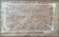
I CAN FOLLOW the schematic in posts #1 and #4, and in those schematics one side of the mains supply is almost DIRECTLY CONNECTED to the amplifier "common" (negative) side of the amplifier circuit. While that is not a problem for the amplifier it can certainly be a serious shock hazard if that side of the mains connection is not connected to the mains NEUTRAL side, and you touch anything connected to the common of the internal electronic circuit.
ALSO, one side of the mains power is present on the "common" of the radio internal circuit. THAT provides the hazard!!
SO, EVEN IF the mains connection is a polarized connector, it is POTENTIONALLY UNSAFE, since any extension cord that is incorrectly wired will place the amplifier common at the mains supply "HOT SIDE" voltage.

My caution is that the arrangement will perform quite well no matter which way the mains power is connected, but there may still be the shock hazard if the mains connection is reversed. An isolatio transformer in either the mains supply line, OR the guitar pickup line, can allow safe operation. BY "SHOCK HAZARD" I mean ELECTROCUTION, possibly. Or a shock nasty enough to cause the TS to drop the guitar.
 
Last edited:

AnalogKid

Joined Aug 1, 2013
12,276
At the top of rectifier SD1 is approx. 160 VDC that is *not* isolated from the mains. Any coupling transformer into or out of this circuit **must** be rated for AC mains isolation.

Else, death.

ak
 
At the top of rectifier SD1 is approx. 160 VDC that is *not* isolated from the mains. Any coupling transformer into or out of this circuit **must** be rated for AC mains isolation.

Else, death.

ak
Certainly whatever transformer is used to provide the isolation indeed MUST BE RATED for at least that voltage. MOST transformers of the required voltage and current rating will be, BUT they need to have that rating lable to make it legal. and satisfy the folks who inspect the equipment.

I would not consider ownng a non-isolated amplifier! Aside from the isolation issue, what other shortcuts would have been taken??
 

Thread Starter

Jsprite7660

Joined Jan 9, 2024
62
Ok thanks all! so all of that being said, I am going to wire the 1/4" jack, that the guitar will plug into, across the primary of the Shure 51A303, and the secondary will connect to the preamp(which again, is separately powered from the radio, using a one spot 9V cable)

How does that sound?
 

MisterBill2

Joined Jan 23, 2018
28,306
Post #13 makes sense. I did not follow the link to the transformer, so I do not know if it has adequate insulation or not.
SAFER will be to use an isolation transformer on the mains side of the radio power connection. THAT will make the entire radio safer.
 
Top