P18F4520 Assembly Exercise

Thread Starter

Sparky49

Joined Jul 16, 2011
833
Hi all,

I thought I would post here, as this is related to uni stuff, rather than my own projects.

This is an exercise I have spent several hours trying to figure out what to do. None of my classmates can figure it out either. Any guidance would be really appreciated.

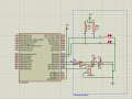
We were tasked to program a PIC 18F4520 in assembly on Proteus. Using just port D, we had to have two toggle switches which would light up a respective output LED. If both switches were closed, both LEDs would illuminate and a buzzer would also sound.

Here is the schematic I drew up:


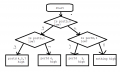
I started by drawing out a logic table, from the schematic above, a closed switch would make a low and an open a high. From there I sketched out a rough flowchart, which is below:


Here is my program. I assume it boils down to a misunderstanding about a function.

Rich (BB code):
;====================================================================
; Main.asm file generated by New Project wizard
;
; Created:   Thu Feb 6 2014
; Processor: PIC18F4520
; Compiler:  MPASM (MPLAB)
;====================================================================

;====================================================================
; DEFINITIONS
;====================================================================
		LIST P=18F4520
		#include <P18f4520.INC>                ; Include register definition file

;====================================================================
; VARIABLES
;====================================================================

;====================================================================
; RESET and INTERRUPT VECTORS
;====================================================================

		ORG		0X0000		;ORG
		
		
		GOTO	MAIN
		
MAIN

		MOVLW	0x0F
		MOVWF	TRISD


LOOP	BTFSC	PORTD,0
		GOTO	DEC2
		GOTO	DEC1
	
DEC1
		BTFSC	PORTD,1
		GOTO	LEDAO
		GOTO	NOTO
		
DEC2	BTFSC	PORTD,1
		GOTO	BUZO
		GOTO	LEDBO
		
		
LEDAO	BCF		PORTD,5
		BCF		PORTD,7
		BSF		PORTD,4
		GOTO	LOOP
		
LEDBO	BCF		PORTD,4
		BCF		PORTD,7
		BSF		PORTD,5
		GOTO	LOOP
		
BUZO	BSF		PORTD,4
		BSF		PORTD,5
		BSF		PORTD,7
		GOTO	LOOP
		
NOTO	BCF		PORTD,4
		BCF		PORTD,5
		BCF		PORTD,7
		GOTO	LOOP
		
		
;====================================================================
      END
Any pointers, or helpful hints would be much appreciated. I've tried not to waffle, but may have missed out some information. If you need any clarification or extra information, just ask. :)

Regards,

Sparky
 

Attachments

Last edited by a moderator:

JohnInTX

Joined Jun 26, 2012
4,787
BUZ0 is entered when both switches are open (reading '1'), turning on the LEDs and buzzer. I think in DEC1 and DEC2, BTFSC should be BTFSS?

That's all I looked at.
 

MaxHeadRoom

Joined Jul 18, 2013
30,808
This work?
Max.
Rich (BB code):
    ORG 0X0000 ;ORG


        goto MAIN

MAIN:

        movlw 0x0F
        movwf TRISD


Loop:
        btfsc     PORTD, 0
        bsf        PORTD,    4    ;LED1
        
        btfsc    PORTD, 1            
        bsf        PORTD, 5    ;LED2
        
        movlw    0x03
        xorwf    PORTD
        btfsc    STATUS, Z
        bsf        PORTD, 7
        btfss    PORTD, 0
        bcf        PORTD, 4
        btfss    PORTD, 1
        bcf        PORTD, 5
        xorwf    PORTD
        btfsc    STATUS, Z
        goto     Loop
        bcf        PORTD, 7
        goto     Loop
        end
 

Thread Starter

Sparky49

Joined Jul 16, 2011
833
Thanks for the replies guys.

I will have to check tomorrow, as we are not given copies of Proteus ourselves.

Whilst I appreciate the code Max, I would like to try to get an understanding of it for myself. :)

Perhaps I could ask about the STATUS, Z?

What does that mean/do?

Regards,

Sparky
 

MaxHeadRoom

Joined Jul 18, 2013
30,808
the XORWF does an exclusive OR with a register or other, and the result of the XOR is recorded by the ZERO (or NON-ZERO) result by the Z flag in the STATUS register.
So a conditional jump can be done by looking at the flag, in this case, Are both inputs,0 & 1 = ON of the PORTD?
I haven't tested the code, but it should be something to look at and maybe build on?
Max.
 

JohnInTX

Joined Jun 26, 2012
4,787
It looks like the BTFSC in LOOP should also be BTFSS - the switch logic looks inverted throughout.

Also, your BSF/BCF should be on LATx, not PORTx to avoid read-modify-write issues.

Consider formatting your code like Max shows, its much easier to read and find errors.

A further way to make code easier to read is to use #defines to specify IO - for example:
Rich (BB code):
#define SW1in_ PORTD,0 ; trailing underscore means its active low
..
#define BUZZout LATD,7  ; no underscore; 1=buzz
#define LED1out LATD,4  ; 1= LED on

then use:
 btfss SW1in_
 goto SW1true ; SW1 is pushed
 goto SW1false ; SW1 is open

and:
 bsf BUZZout ; buzzer ON
 bsf LED1out  ; LED on
Besides being easier to read, if you move something to another IO pin, you just have to change the #define, not pour through the code for all instances of it. It also ensures consistency.

No comments? Comments in the code are most useful for others reading the code but especially to you while you are writing the code. I usually comment code blocks before coding them. If the block descriptions make sense, all I have to do is code that block to fit the description. I find that many, including myself, don't always go back to fully comment code once its working, making it tough to come back later for a revision or to re-use the code.

Have fun!
 
Last edited:

ericgibbs

Joined Jan 29, 2010
21,569
hi,

PORTD.7 never turns ON in post #3 code.

Also if I read the OP's text, the Input switch pins are active Low, not high as in #3

E

Rich (BB code):
main:
    MOVF PORTD,W
    ANDLW 0x03
    BTFSC STATUS,Z
    GOTO buzz    
    BCF PORTD,7
    
    BTFSC PORTD,0
    BCF PORTD,4
    BTFSS PORTD,0
    BSF PORTD,4

    BTFSC PORTD,1
    BCF PORTD,5
    BTFSS PORTD,1
    BSF PORTD,5
    
     GOTO main
buzz:
    BSF PORTD,7
        
        GOTO main
 

Thread Starter

Sparky49

Joined Jul 16, 2011
833
Thanks guys.

Yep, I was kicking myself after not putting comments into it. Up to now, the programs have been simple enough, so I added comments after I got a working program. I see now hat it certainly more beneficial to add them whilst programming.

A couple of questions, why does Eric's program not need to define I/O's?

And Max, are you saying:

BTFSC STATUS,Z

Should be

BTFSS STATUS, Z

Regards,

Sparky

P.S. Thanks for the sample programs. It is most interesting to see the different ways a program can be set out.
 

MaxHeadRoom

Joined Jul 18, 2013
30,808
I made a bit of a slip by not noticing that the switches were active low instead of active high, if the reverse were the case the program should work, I did not re work it for active high.
You can either predefine a port etc or use the explicit name and bit address, the define makes it a more readable code and easier to modify, if required.


A couple of questions, why does Eric's program not need to define I/O's?

And Max, are you saying:

BTFSC STATUS,Z

Should be

BTFSS STATUS, Z

Regards,

Sparky

P.S. Thanks for the sample programs. It is most interesting to see the different ways a program can be set out.
Give a task to ten different programmers and you will get ten different results, if the program runs, none of them wrong just different methods used.
Did you get the program to run, if so what was the code result?
Max.
 

Thread Starter

Sparky49

Joined Jul 16, 2011
833
Unfortunately, no, I haven't managed to test the code.

Went in on Friday, put my USB stick (with the program in a word document) into the computer. Then I realised it wasn't switched on, so I booted it up, and it tried to boot an OS I had on the USB stick.... -_-

We're not allowed in on weekends, so I'll try it tomorrow.

Sparky
 
Top