 Facebook
 Google
 GitHub
 Linkedin
Another one for the brain trust... not sure if i've asked around about this circuit before.
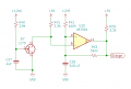
this is a timer on an early two-way load management device. The purpose is apparently to indicate if the power has been off long enough the NVRAM contents may be suspect (if the code sees an output state change upon restart, it clears the NVRAM rather than risk bad data being available for download.
My question is, what is the purpose of JFET Q7? Why not just connect C37 / R40 directly to pin 8?
Attachments
-
 14.4 KB Views: 21


