Optocouple interface vs SN74LS07 Interface

Thread Starter

Xavier Pacheco Paulino

Joined Oct 21, 2015
728
Hello,

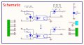
I attach an optocoupler interface based on 4N25, which is used to convert 5V TTL to 12V. It has been tested and it works. It was made several years ago. Now, I want to do something similar, instead of 12V output, I need 24V. So I suppose the only thing that changes is the supply voltage.

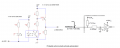
I also attach a circuit using the 74LS07. My question is, which one is better? I'm trying to design another interface like the 4N25 one, but I'm curious about the new enhaced chips nowadays that could be another solution.
 

Attachments

danadak

Joined Mar 10, 2018
4,057
The 4N25 is a good solution unless you are pushing speed limits, its isolation
an excellent characteristic the 74LS07 does not share. But the 74LS07 is
faster.

Regards, Dana.
 

AlbertHall

Joined Jun 4, 2014
12,343
If you need isolation and 100us propagation delay isn't a problem then the 4N25 is the way to go.
If you don't need isolation then the 7407 will do the job but will use more PCB area unless you will be using all the gates in the package.
 

AlbertHall

Joined Jun 4, 2014
12,343
In the image you posted in post #3 the emitter and collector should be swapped. The collector should connect to the voltmeter and the emitter should connect to the positive 12V supply.
 

AnalogKid

Joined Aug 1, 2013
10,986
Q2 is in the circuit upside-down; the emitter goes to 12 V.
Increase R2 to 10K to increase the Q2 base current and assure saturation.
The 7407 output transistor is rated for 30 V, but operating it there will decrease its reliability.

ak
 

AlbertHall

Joined Jun 4, 2014
12,343
In the diagrams in post #1 and #3 the designations for R3 and R4 are swapped so the resistor to change is R3 in the post #1 diagram and R4 in post #3.
 

AnalogKid

Joined Aug 1, 2013
10,986
Post #1
Image 4N25.PNG
Left-side schematic
R3

Increasing R3 to 10K allows more of the current through R4 to come through the Q2 base-emitter junction (when Q2 is corrected), allowing for more "firm" saturation and a lower voltage drop.

ak
 

AnalogKid

Joined Aug 1, 2013
10,986
Yes, maybe. The max. collector current for the 4N25 is not specified on the datasheet, but plots that include collector current stop at 10 mA. For reliable operation, the max collector current in your circuit should be no more than one-half of that max value, 5 mA. If that is enough, then you do not need an additional transistor. If your circuit will have an LED se in the schematic in post #15, the LED current plus whatever else is connected to the opto should not exceed 5 mA.

ak
 
Top